RF and/or microwave energy conveying structure, and an invasive electrosurgical scoping device incorporating the same

a technology of electromagnetic energy conveying structure and invasive electrosurgical scoping device, which is applied in the direction of coupling device connection, catheter, surgery, etc., to achieve the effect of reducing or eliminating power reflection

Active Publication Date: 2017-08-03
CREO MEDICAL LTD
View PDF4 Cites 27 Cited by
  • Summary
  • Abstract
  • Description
  • Claims
  • Application Information

AI Technical Summary

Benefits of technology

[0023]The electrosurgical instrument may be introduced to the distal end of the instrument channel via a catheter that is fed through the instrument channel. The connection collar may be mounted on the catheter, and may comprise a cylindrical body having a diameter greater than the diameter of the catheter. The outer surface of the cylindrical body may be in close proximity (e.g. touching) the innermost layer of the energy conveying structure, to ensure secure engagement between the first contact and first terminal and between the second contact and second terminal. The first terminal and second terminal may project inwards from the innermost layer slightly. The connection collar may include a shoulder for abutting the stop flange to securely locate the collar in position.
[0024]The electrosurgical instrument may include an extension sleeve that extends axially away from the connection collar towards the bipolar transmission structure at the distal end of the electrosurgical instrument. In use, the extension sleeve may thus protrude out of the end of the instrument channel. The extension sleeve may comprise a tube of dielectric material, and may carry conductive structures (e.g. conductive rods or the like) which provide electrical connection between the first contact and first conductive element and between the second contact and second conductive element respectively. The conductive structure may comprise a short length of conventional coaxial cable.
[0025]If the electrosurgical instrument is arranged to receive microwave energy from the energy conveying structure, it may be desirable for the electrosurgical instrument to be configured to match the impedance of the energy conveying structure with the impedance of the electrosurgical instrument at the frequency of microwave energy. This may be achieved by selecting the geometry (e.g. sizes and / or shapes) of the first and second terminals, the connection collar and the connection between the conductive structure of the extension sleeve and the bipolar transmission structure, e.g. based on microwave field simulations, experimental measurements, etc. Providing an impedance match reduces or eliminates power reflections at transition points between different geometries in the energy conveying path, and thus may enable power to be delivered more efficiently to the electrosurgical instrument. The conductive structure in the extension sleeve may have an electrical length of a multiple of half a wavelength of the microwave energy to render it effectively invisible in any impedance matching geometry.

Problems solved by technology

It is an ongoing challenge to provide both sufficient power and the additional supplies or components mentioned above in a compact enough form to fit within an instrument channel whilst maintaining flexibility and restricting power loss to acceptable (i.e. safe) levels.

Method used


Image

  • RF and/or microwave energy conveying structure, and an invasive electrosurgical scoping device incorporating the same
  • RF and/or microwave energy conveying structure, and an invasive electrosurgical scoping device incorporating the same
  • RF and/or microwave energy conveying structure, and an invasive electrosurgical scoping device incorporating the same

Examples


Embodiment Construction

; FURTHER OPTIONS AND PREFERENCES

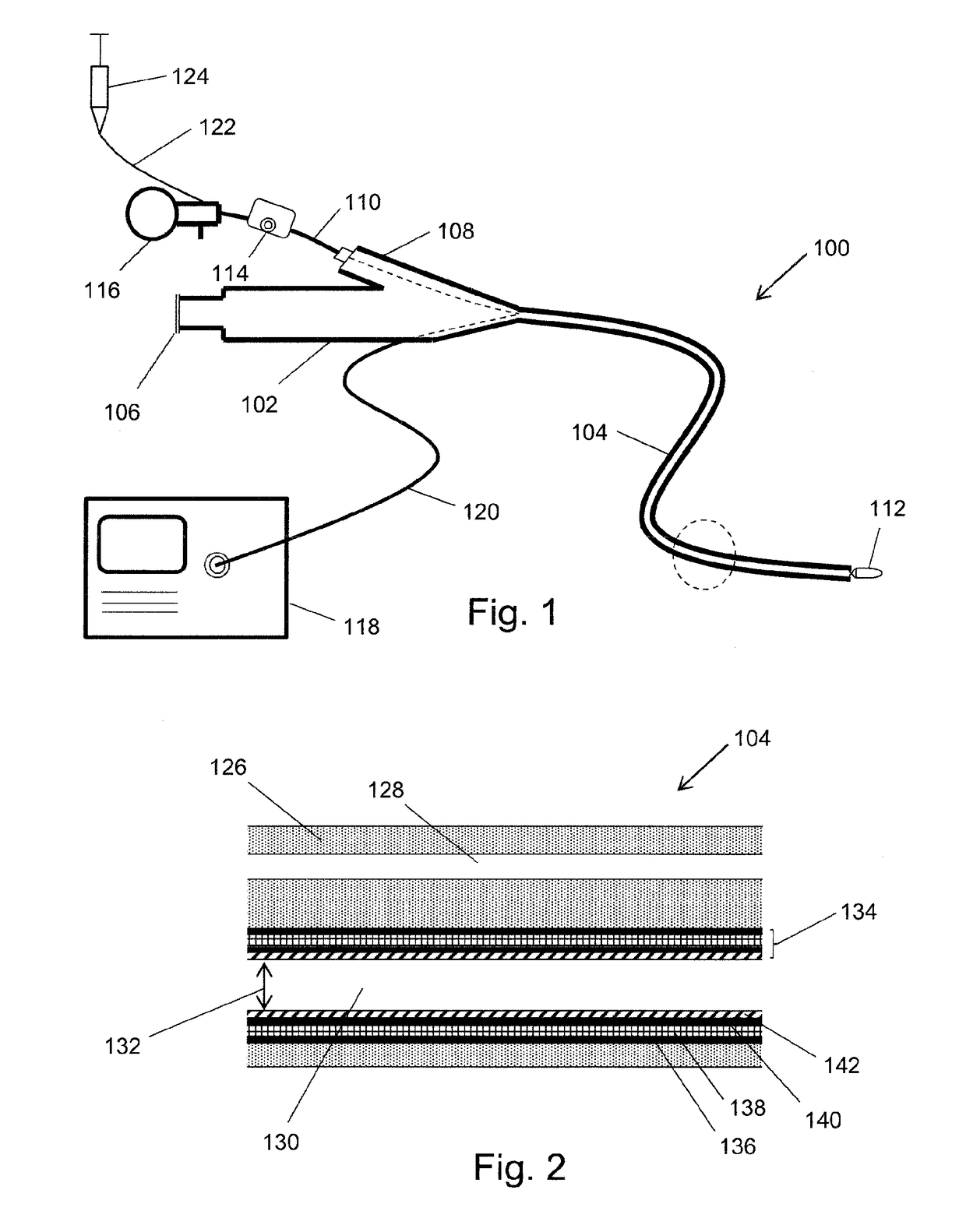
[0046]FIG. 1 is a schematic view of an invasive electrosurgical system 100 in which the present invention may be used. The system 100 comprises an endoscope that has a main body 102 and a flexible insertion tube 104 extending from the main body 102, which is suitable for insertion into the body to access the treatment site. The insertion tube 104 houses various channels, e.g. an instrument channel and an observation channel. The observation channel may carry optical equipment suitable for delivering an image of the treatment site to an observation port 106. The instrument channel 104 may include means for conveying radiofrequency (RF) and / or microwave energy. An electrosurgical generator 118 is connected to the main body 102 via a cable 120 which carries the RF and / or microwave energy into the main body 102 and is electrically connected to the energy conveying means in the instrument channel. This electrical connection may be provided by a “T” connec...


PUM


Abstract

Embodiments of the invention provide an energy conveying structure for delivering RF and/or microwave energy to an electrosurgical instrument, where the energy conveying structure is incorporated into an insertion tube of a surgical scoping device (e.g. endoscope, laparoscope or the like). The insertion tube is a flexible conduit that is introduced into a patient's body during an invasive procedure, and can include an instrument channel and an optical channel. The energy conveying structure may be a layered coaxial structure that formed a liner that fits within the scoping device, e.g. within an instrument channel. Alternatively, the energy conveying structure may be a coaxial structure integrally formed as part of the flexible conduit.

Description

FIELD OF THE INVENTION[0001]The invention relates to an energy conveying structure (e.g. waveguide or cable) for carrying radiofrequency (RF) and / or microwave energy from an electrosurgical generator to an electrosurgical instrument. In particular, the invention concerns electrosurgical instruments that are used in invasive procedures, e.g. introduced through an instrument channel of an endoscope, laparoscope or the like. For example, the invention may find particular use in natural orifice transluminal endoscopic surgery (NOTES).BACKGROUND TO THE INVENTION[0002]Electrosurgical instruments are instruments that are used to deliver radiofrequency and / or microwave frequency energy to biological tissue, for purposes such as cutting biological tissue or coagulating blood. Radiofrequency and / or microwave frequency energy is typically supplied to the electrosurgical instrument using a cable. Conventional cables used for this purpose have a coaxial transmission line structure comprising a s...

Claims


Application Information

Patent Timeline
Patent Type & Authority Applications(United States)
IPC IPC(8): A61B18/14H01R24/38A61B18/12A61B18/18A61B17/00
CPCA61B18/1492H01R2103/00A61B17/00234A61B18/1206H01R24/38A61B2017/0034A61B2017/00477A61B2017/00929A61B2018/00178A61B2018/00196A61B2018/126A61B2018/1838A61B2018/1861A61B2018/1892A61B2018/00077A61B2018/00083H01R2201/12A61B18/1815H01R24/58A61B1/018
Inventor HANCOCK, CHRISTOPHER PAULWHITE, MALCOLMULLRICH, GEORGE CHRISTIANWEBB, DAVID EDWARDPRESTON, SHAUNMORRIS, STEVEN
Owner CREO MEDICAL LTD
Why Eureka
Try Eureka