Cooking utensil

A technology of cooking utensils and cooking chambers, applied in kitchen utensils, household utensils, roasters/barbecue grids, etc., can solve problems such as low utilization efficiency, high cost, and poor heat dissipation, and achieve efficient integration, guidance, and improvement Heat dissipation performance, effect of reducing drag

Active Publication Date: 2021-03-12
GUANGDONG MIDEA KITCHEN APPLIANCES MFG CO LTD +1
View PDF5 Cites 1 Cited by
  • Summary
  • Abstract
  • Description
  • Claims
  • Application Information

AI Technical Summary

Problems solved by technology

like figure 2 As shown, the air duct structure 100' failed to fully consider the loss of air duct resistance, the design of the air duct path is unreasonable (many positions do not need to install air ducts), the heat dissipation effect is not good, and the designed air duct cannot be fully utilized, and the utilization efficiency low cost high

Method used


Image

  • Cooking utensil
  • Cooking utensil
  • Cooking utensil

Examples


Embodiment 1

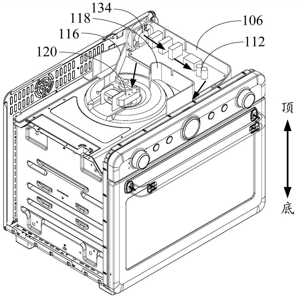
[0072] Such as image 3 and Figure 4 As shown, the first embodiment of the present invention proposes a cooking appliance, including: an air duct structure 100 ;

[0073] Among them, such as image 3 As shown, the airflow inside the air duct structure 100 can be discharged through the air outlet 104 , and the first side wall 106 extends toward the direction of the air outlet 104 , which can play a certain air guiding effect. In addition, since the bottom wall 102 is further provided with a flow guide 108 , and the flow guide 108 extends toward the air outlet 104 , and cooperates with the first side wall 106 to jointly play a role of flow guide.

[0074] In particular, as Figure 4 As shown, the top of the air guide 108 is lower than the top of the first side wall 106, which makes it possible to assemble the heat sink 112 inside the air duct structure 100 during use, and assemble the heat sink 112 on the guide. Flow piece 108 on. With such a design, part of the airflow in...

Embodiment 2

[0078] Such as image 3 and Figure 4 As shown, the second embodiment of the present invention proposes a cooking utensil, including: an air duct structure 100 and a heat dissipation member 112; the air duct structure 100 includes a bottom wall 102, an air outlet 104, a first side wall 106, and a flow guide 108 and support 110.

[0079] Among them, such as image 3 As shown, the airflow inside the air duct structure 100 can be discharged through the air outlet 104 , and the first side wall 106 extends toward the direction of the air outlet 104 , which can play a certain air guiding effect. In addition, since the bottom wall 102 is further provided with a flow guide 108 , and the flow guide 108 extends toward the air outlet 104 , and cooperates with the first side wall 106 to jointly play a role of flow guide.

[0080] In addition, if Figure 4 As shown, the support member 110 is disposed on the bottom wall 102 and protrudes from the bottom wall 102 . In particular, the to...

Embodiment 3

[0086] Such as image 3 and Figure 4 As shown, the third embodiment of the present invention proposes a cooking utensil, including: an air duct structure 100 and a heat dissipation member 112; the air duct structure 100 includes a bottom wall 102, an air outlet 104, an air inlet 114, and a first side wall 106 , the deflector 108 and the support 110 .

[0087] Among them, such as image 3 As shown, the airflow inside the air duct structure 100 can be discharged through the air outlet 104 , and the first side wall 106 extends toward the direction of the air outlet 104 , which can play a certain air guiding effect. In addition, since the bottom wall 102 is further provided with a flow guide 108 , and the flow guide 108 extends toward the air outlet 104 , and cooperates with the first side wall 106 to jointly play a role of flow guide.

[0088] Moreover, when the heat dissipation element 112 is assembled on the support element 110 of the air duct structure 100, the first side ...


PUM


Abstract

The invention provides a cooking utensil. The cooking utensil comprises an air duct structure which comprises a bottom wall, an air outlet, an air inlet, an air inlet and an air outlet, a first side wall which is arranged on the bottom wall and extends towards the air outlet; a flow guide part which is arranged on the bottom wall, and the top of the flow guide part is lower than the top of the first side wall and extends towards the air outlet. The air duct structure is improved, so the first side wall of the air duct structure and the flow guide piece efficiently integrate and guide airflow,resistance borne by a body in the flowing process can be effectively reduced, loss of gas in the flowing process is reduced, the upper surface and the lower surface of the piece to be cooled can be cooled at the same time, and the service life of the piece to be cooled is prolonged; and the heat dissipation performance of the air duct structure is effectively improved.

Description

technical field [0001] The invention relates to the technical field of kitchen appliances, in particular to a cooking utensil. Background technique [0002] As there are more and more types of cooking utensils such as ovens, ovens with small size and high performance are more favored by consumers. In this development process, cooking appliances such as ovens have an increasing demand for heat dissipation, and the heat dissipation effect restricts the development of products. [0003] The heat dissipation methods adopted by related technologies are as follows: figure 1 and figure 2 As shown, among them, figure 2 The arrows in indicate the direction of gas flow. Wherein, two driving components 134' are used to cooperate with the air duct structure 100' having two air ducts to dissipate heat from the electronic board waiting for the heat sink 112'. Such as figure 2 As shown, the air duct structure 100' failed to fully consider the loss of air duct resistance, the desig...

Claims


Application Information

Patent Timeline
IPC IPC(8): A47J37/06
CPCA47J37/0641A47J37/0664
Inventor 裴杰
Owner GUANGDONG MIDEA KITCHEN APPLIANCES MFG CO LTD
Why Eureka
Try Eureka