Mechanical lock mechanism of integrated linkage coordination valve

A technology for mechanical locks and shutters, applied in non-mechanical transmission-operated locks, aircraft doors, building locks, etc., can solve the problems of mechanical lock fatigue life influence, unstable unlocking action, and large compound load, etc., to achieve easy manufacturing and Maintenance, simple structure, reliable unlocking effect

Active Publication Date: 2021-03-12
LANDING GEAR ADVANCED MFG
View PDF5 Cites 2 Cited by
  • Summary
  • Abstract
  • Description
  • Claims
  • Application Information

AI Technical Summary

Problems solved by technology

During the unlocking process of the hydraulic-controlled mechanical lock, the load output by the actuator to make the moving parts start to move also acts on the mechanical lock at the same time, which makes the mechanical lock bear a large composite load, making it very difficult to unlock; and the moment the unlock is just completed , the whole movement mechanism will produce a certain impact vibration, which makes the unlocking action unstable and has a great impact on the fatigue life of the mechanical lock.
[0003] Therefore, the way and structural form of the traditional hydraulic control system to supply hydraulic oil to the mechanical lock mechanism and other actuators at the same time can no longer meet the requirements of modern equipment for easy function realization, high reliability, safety, long life and low maintenance cost.

Method used


Image

  • Mechanical lock mechanism of integrated linkage coordination valve
  • Mechanical lock mechanism of integrated linkage coordination valve
  • Mechanical lock mechanism of integrated linkage coordination valve

Examples


Embodiment Construction

[0045] The present invention will be further described below in conjunction with specific preferred embodiments, but the protection scope of the present invention is not limited thereby.

[0046] For the convenience of description, the relative positional relationship of each component, such as: the description of up, down, left, right, etc., is described according to the layout direction of the drawings in the specification, and does not limit the structure of this patent.

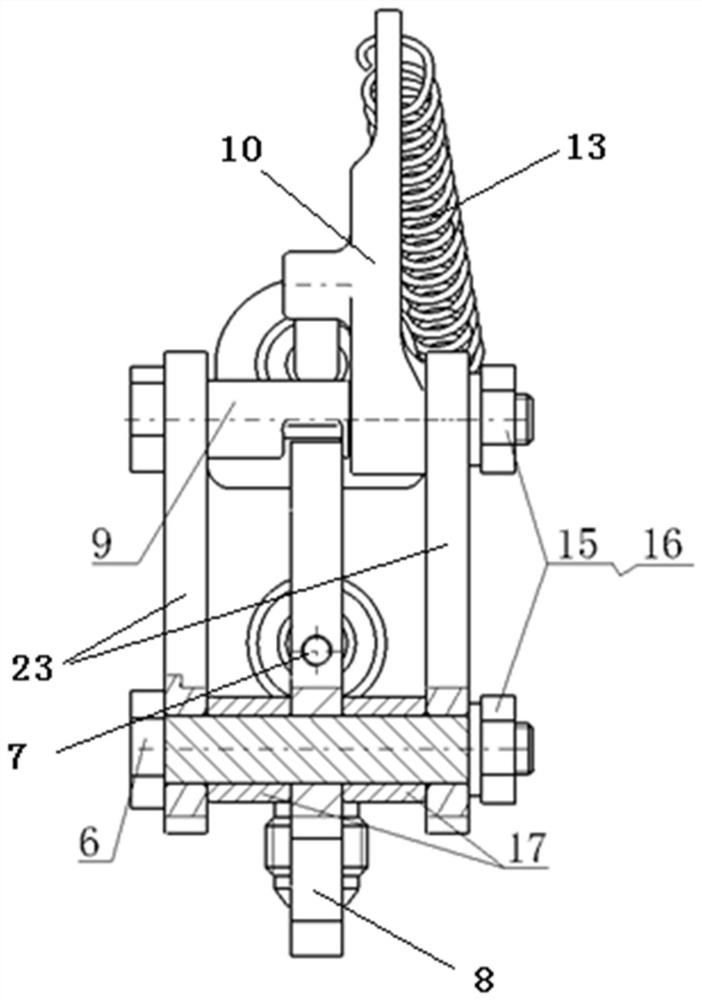
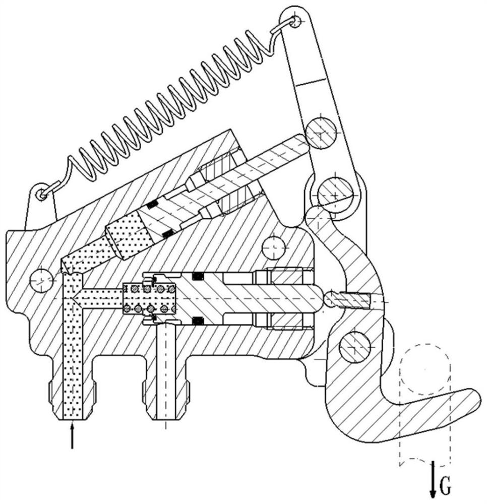
[0047] Such as figure 1 - Figure 18 As shown, the present invention adopts the integrated design technology, and integrates the hydraulically controlled unlocking actuator A and the coordinating valve B into the mechanical lock mechanism. Specifically, an embodiment of the present invention includes a lock housing 1, an unlocking piston rod 11, a coordination valve rod 4, a second guide sleeve 12, a first guide sleeve 5, a lock hook 8, a top post 7, a lock post bolt 9, Rocking arm 10, hinge bolt 6, spa...


PUM


Abstract

The invention discloses a mechanical lock mechanism of an integrated linkage coordination valve. The mechanism comprises a lock shell, and an unlocking actuating cylinder and a coordination valve arearranged on the lock shell; a rocker arm and a lock hook are arranged at the outer ends of the unlocking actuating cylinder and the coordination valve, one end of the rocker arm is installed on a lockcolumn bolt, a tension spring is arranged between the other end of the rocker arm and the lock shell, an unlocking piston rod of the unlocking actuating cylinder abuts against the middle of the rocker arm, the lock column bolt is in clearance fit with the lock shell, and the lock column bolt and the rocker arm form a linkage body; a lock head of the lock hook abuts against or is separated from the lock column bolt, a jacking column is fixedly connected to the rocker arm between the lock head and the hinge bolt, and the coordination valve rod is jacked against or separated from the jacking column. Rodless cavities of the unlocking actuator cylinder and the coordination valve are communicated with a hydraulic oil path through an oil inlet pipe nozzle hole, and an oil outlet pipe nozzle holeis communicated with an execution component; during locking, the coordinating valve rod closes the oil outlet pipe nozzle hole, and during unlocking, the coordinating valve rod extends out, so that the rodless cavity of the coordinating valve is communicated with the oil outlet pipe nozzle hole.

Description

technical field [0001] The invention relates to a hydraulically controlled mechanical lock mechanism, in particular to a mechanical lock mechanism integrating linkage coordination valves. Background technique [0002] In the movement mechanism of modern large-scale equipment, its control system is equipped with lock mechanism and executive components, such as the position lock of the aircraft landing gear retractable system, retractable actuator or cabin door lock and opening and closing actuator, etc., to ensure The equipment is normal and safe to use. At present, when the equipment control system is a hydraulic control system, the lock mechanism is usually a hydraulic-controlled mechanical lock mechanism. In order to simplify the hydraulic control system, the traditional hydraulic control system supplies hydraulic oil to the hydraulic-controlled mechanical lock mechanism and the execution parts at the same time when unlocking and performing movements. During the unlockin...

Claims


Application Information

Patent Timeline
Patent Type & Authority Applications(China)
IPC IPC(8): B64C1/14B64C25/26E05B51/02
CPCB64C1/1407B64C25/26E05B51/02
Inventor 邓晓山黄立新禹新鹏鲁德发李兆昕关维刘建波
Owner LANDING GEAR ADVANCED MFG
Why Eureka
Try Eureka