Body Structure and Vehicle
A body and beam technology, which is applied to the body structure and the vehicle field using the body structure, can solve the problems that the overall size of the battery pack cannot be increased, and the battery life cannot be improved, so as to achieve the effect of improving the battery life
- Summary
- Abstract
- Description
- Claims
- Application Information
AI Technical Summary
Problems solved by technology
Method used
Image

Examples
Embodiment Construction
[0041] Specific embodiments of the present disclosure will be described in detail below in conjunction with the accompanying drawings. It should be understood that the specific embodiments described here are only used to illustrate and explain the present disclosure, and are not intended to limit the present disclosure.
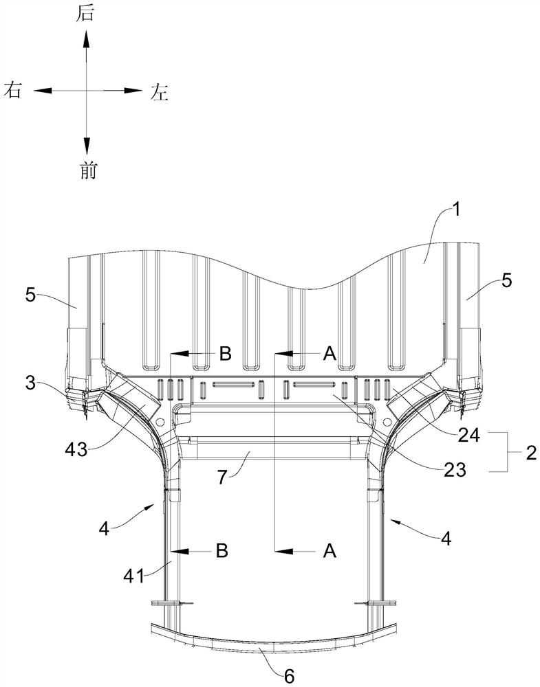
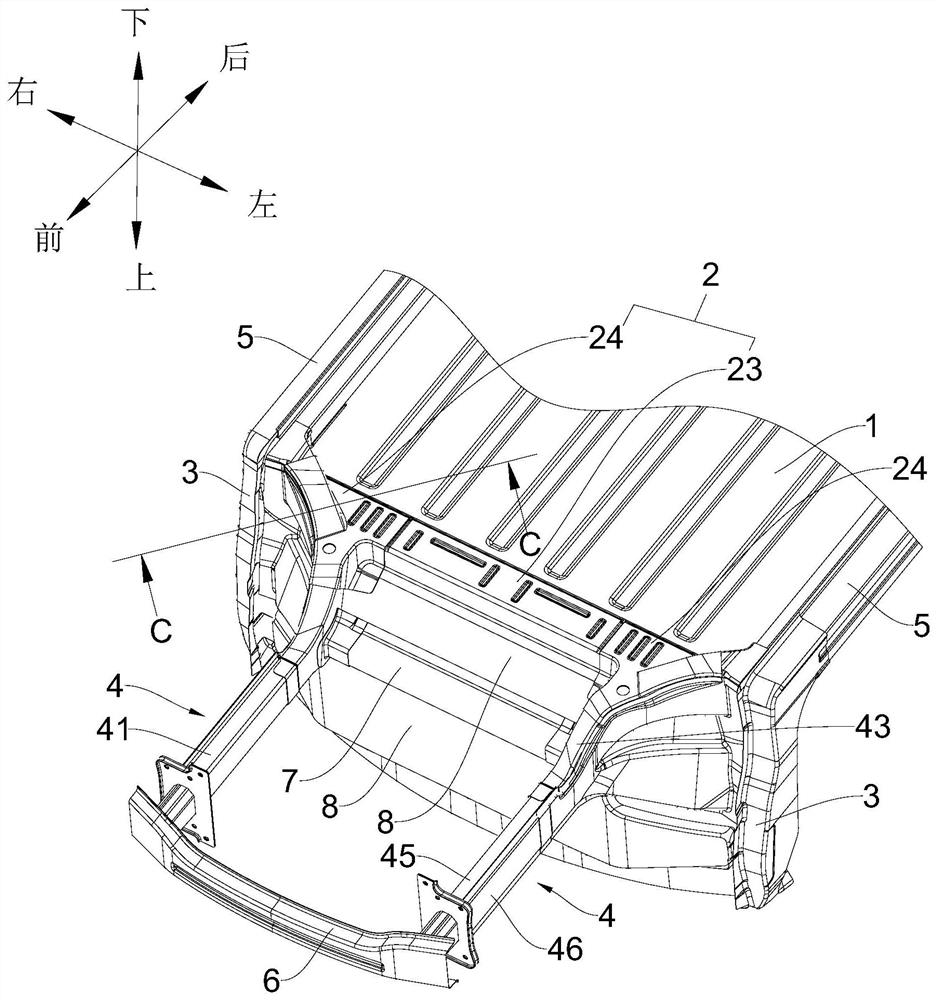
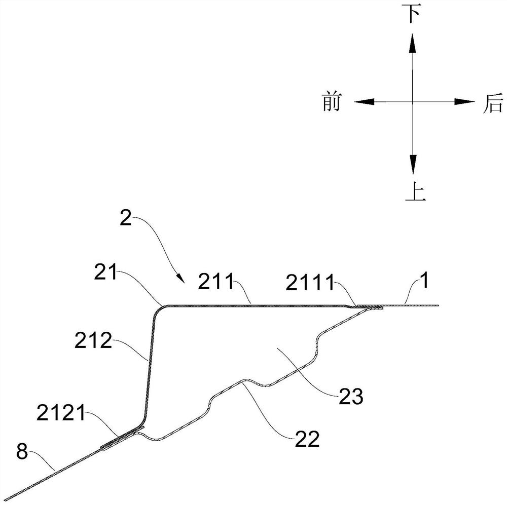
[0042] In this disclosure, unless stated otherwise, the orientation words used such as "up, down, left, right, top, bottom, front, rear" are usually relative to the normal driving state of the vehicle, specifically Generally speaking, when the vehicle is running normally, the direction towards the vehicle roof is "top" or "up", the direction towards the vehicle floor is "bottom" or "down", the direction towards the left wheel of the vehicle is "left", and the direction towards the right wheel of the vehicle is "left". The direction of the vehicle is "right", the direction towards the front of the vehicle is "front", and the direction towards the rear is "rear...
PUM
 Abstract
Description
Claims
Application Information