Supercharge Your Innovation With Domain-Expert AI Agents!

A multi-class vnf deployment method based on betweenness centrality

An intermediary and server node technology, applied in the field of communication, can solve the problems of inappropriate VNF deployment, inability to effectively reduce the bandwidth occupation of multiple service flows, etc., and achieve the effect of reducing bandwidth occupation

Active Publication Date: 2021-06-25
BEIHANG UNIV
View PDF5 Cites 0 Cited by
  • Summary
  • Abstract
  • Description
  • Claims
  • Application Information

AI Technical Summary

Problems solved by technology

[0005] The purpose of the present invention is to provide a multi-type VNF deployment method based on betweenness centrality (Betweeness Centrality, BC), so as to alleviate the situation that none of the existing VNF deployment methods is suitable for implementing VNF deployment in a multi-stream transmission network, Therefore, it is impossible to effectively reduce the technical problem of bandwidth occupation of multiple service flows in the network

Method used


Image

  • A multi-class vnf deployment method based on betweenness centrality
  • A multi-class vnf deployment method based on betweenness centrality
  • A multi-class vnf deployment method based on betweenness centrality

Examples


Embodiment 1

[0037] According to an embodiment of the present invention, an embodiment of a plurality of VNF deployment methods based on intermediary center is provided, and it is to be explained that the steps shown in the drawings may be in a computer such as a set of computer executable instructions. The system is executed and, although a logical order is shown in the flowchart, in some cases, the steps shown or described in order of different from the order herein can be performed.

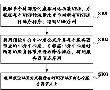
[0038] figure 1 A flow diagram of a plurality of VNF deployment methods based on intermediary center, such as the embodiment of the present invention, such as figure 1 As shown, the method includes steps S101 to step S103:

[0039] Step S101, acquire a plurality of virtual network functions VNF to be deployed, and sequencing all VNFs according to the flow rate change rate of each VNF to obtain a VNF sequence;

[0040] In the embodiment of the present invention, the flow rate change rate Refers to the bandwid...

Embodiment 2

[0112] The embodiment of the present invention provides a multi-class VNF deployment device based on intermediary center, which is mainly used for performing an intermediary center based on the above-described content of the above content. The class VNF deployment method, and the plurality of VNF deployment devices based on intermediary center based on the embodiments of the present invention are specifically described below.

[0113] Figure 4 A structural diagram of a plurality of VNF deployment devices based on intermediary center based on embodiments of the present invention. Such as Figure 4 As shown, the multi-class VNF deployment device based on the intermediary center, mainly includes: obtaining the sorting unit 11, calculating the sorting unit 12, and deploying units 13, wherein:

[0114] The sort unit 11 is obtained for acquiring the virtual network function VNF to be deployed, and sequencing all VNFs according to the flow rate change rate of each VNF to obtain a VNF seq...


PUM


Abstract

The present invention provides a multi-type VNF deployment method based on betweenness centrality, which relates to the technical field of communication, and includes: first obtaining a plurality of virtual network function VNFs to be deployed, and performing all VNFs according to the traffic change rate of each VNF Sort in descending order to obtain the VNF sequence; then use the preset betweenness centrality formula to calculate the betweenness centrality of each server node, and sort all the server nodes in descending order according to the betweenness centrality to obtain the server node sequence; finally follow the preset deployment method Deploy all VNFs to each server node. In the present invention, by deploying the VNF with a large traffic change rate on the server node with high betweenness centrality, the VNF with a large traffic change rate can be closer to the source nodes of different service flows, so that the service flow can be kept low in the network. Stream speed transmission, so as to achieve the purpose of reducing the bandwidth occupation of multiple service streams.

Description

Technical field [0001] The present invention relates to the field of communication technologies, in particular, to a plurality of VNF deployment methods based on intermediary center. Background technique [0002] VNF (Virtual Network Function, Virtual Network Function) Deployment refers to the logical network service diagram described based on SFC (ServiceFunction Chain, Business Chain), using a specific deployment algorithm, or using the characteristics of the logical network service diagram and the underlying physical network diagram Map the logical network service is valid to the bottom network. The existing VNF deployment methods mainly include the following categories: random deployment methods, shortest SFC path deployment methods, and VNF deployment algorithms based on specific targets. [0003] Due to the three types of VNF deployment methods, the random deployment method and the shortest SFC path deployment method, the bandwidth changes from VNF processing traffic are ig...

Claims


Application Information

Patent Timeline
Patent Type & Authority Patents(China)
IPC IPC(8): H04L12/24H04L12/729H04L45/125
CPCH04L41/0893H04L45/125
Inventor 刘锋孙杰张连连石定元
Owner BEIHANG UNIV
Features
  • R&D
  • Intellectual Property
  • Life Sciences
  • Materials
  • Tech Scout
  • Unparalleled Data Quality
  • Higher Quality Content
  • 60% Fewer Hallucinations
Learn More