
LED lamp which is energy-saving and good in heat dissipation effect
A technology of LED lamps and heat dissipation effects, which is applied in the direction of lighting and heating equipment, components of lighting devices, cleaning methods using tools, etc., can solve problems such as insufficient heat dissipation effects, constant cleaning, and unsightly LED lights, etc., and achieve structural Reasonable, reduce the aging speed, accelerate the discharge effect
- Summary
- Abstract
- Description
- Claims
- Application Information
AI Technical Summary
Problems solved by technology
Method used
Image

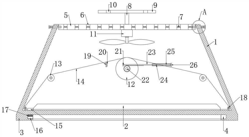

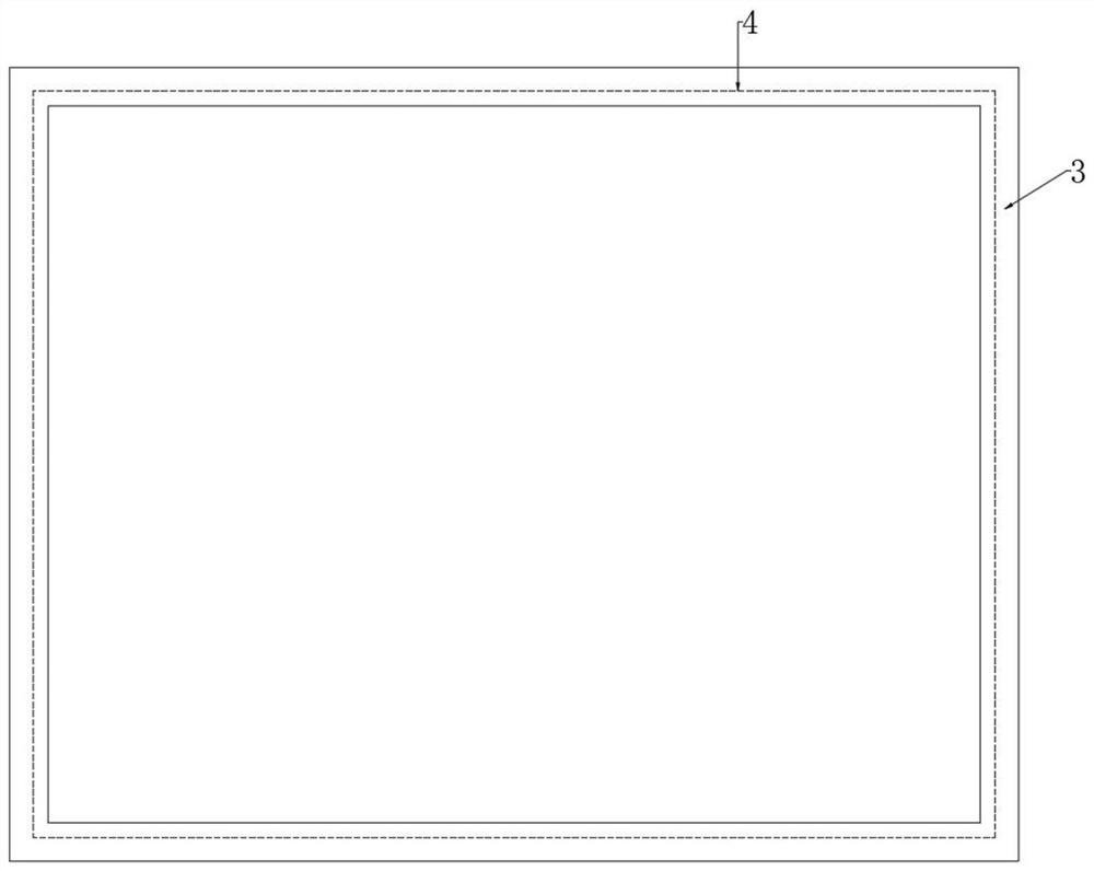
Examples
Embodiment Construction
[0024] The following will clearly and completely describe the technical solutions in the embodiments of the present invention with reference to the accompanying drawings in the embodiments of the present invention. Obviously, the described embodiments are only some, not all, embodiments of the present invention.
[0025] In describing the present invention, it should be understood that the terms "upper", "lower", "front", "rear", "left", "right", "top", "bottom", "inner", " The orientation or positional relationship indicated by "outside", "front end", "rear end", "both ends", "one end" and "the other end" are based on the orientation or positional relationship shown in the drawings, and are only for the convenience of describing this The invention and the simplified description do not indicate or imply that the device or element referred to must have a specific orientation, be constructed and operate in a specific orientation, and thus should not be construed as limiting the p...
PUM
 Abstract
Description
Claims
Application Information