Electric Machine for Driving a Motor Vehicle

Pending Publication Date: 2022-06-23
ZF FRIEDRICHSHAFEN AG
View PDF0 Cites 0 Cited by
  • Summary
  • Abstract
  • Description
  • Claims
  • Application Information

AI Technical Summary

Benefits of technology

[0004]Example aspects of the present invention can assist with better dissipating waste h

Problems solved by technology

Due to the fact that the air duct and the fluid duct are formed by the stator cooling bush system, a low number and complexity of componen

Method used


Image

  • Electric Machine for Driving a Motor Vehicle
  • Electric Machine for Driving a Motor Vehicle
  • Electric Machine for Driving a Motor Vehicle

Examples


Embodiment Construction

[0026]Reference will now be made to embodiments of the invention, one or more examples of which are shown in the drawings. Each embodiment is provided by way of explanation of the invention, and not as a limitation of the invention. For example, features illustrated or described as part of one embodiment can be combined with another embodiment to yield still another embodiment. It is intended that the present invention include these and other modifications and variations to the embodiments described herein.

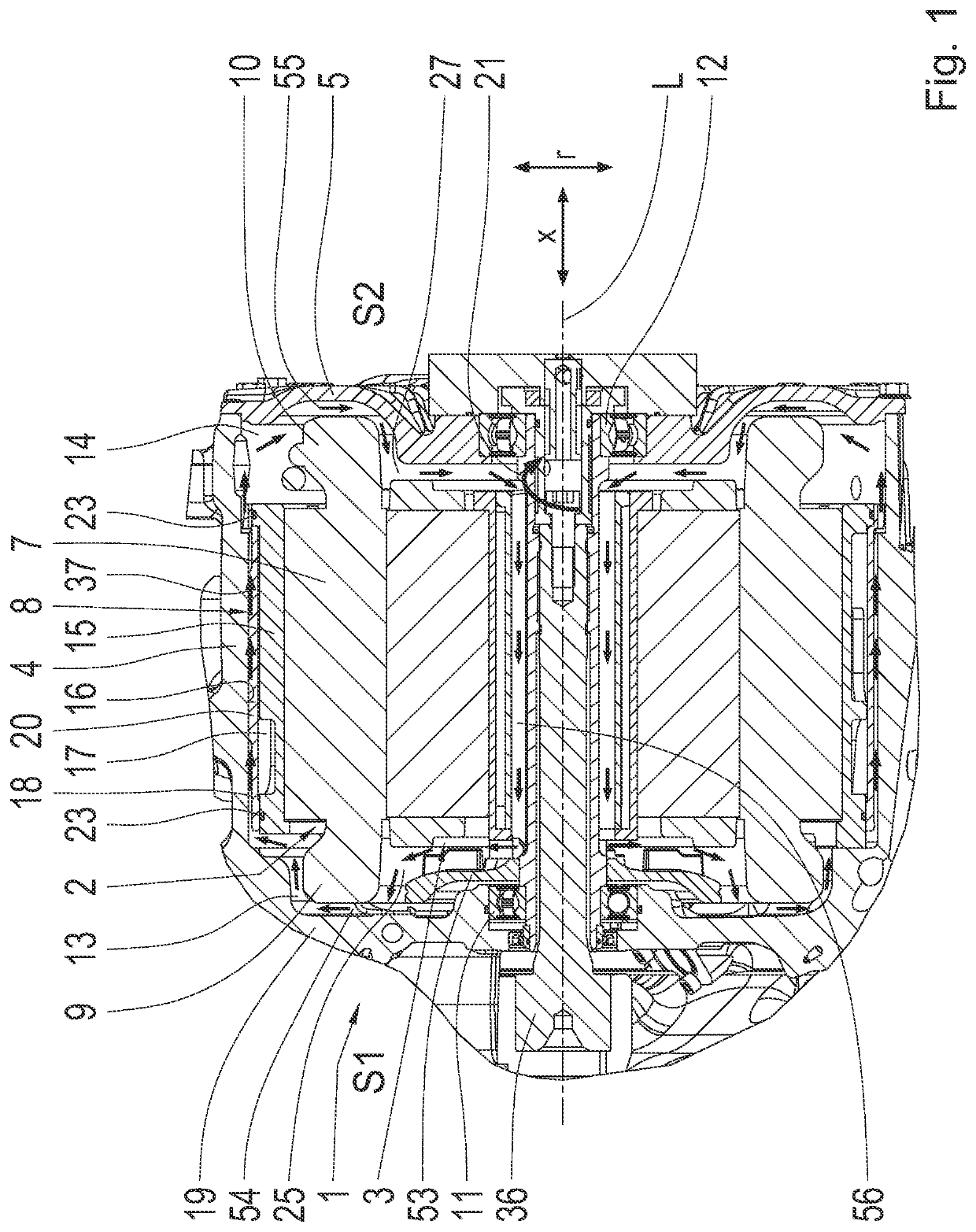
[0027]FIG. 1 shows an electric machine 1 having a stator 2 and having a rotor 3. The electric machine 1 also includes a housing 4 and a housing cover 5. The electric machine 1 can be operated as a motor and as a generator. The electric machine 1 can drive a motor vehicle 6 / 38, which is shown in FIG. 6 and FIG. 7, respectively.

[0028]When the electric machine 1 is operated as a motor, a time-varying voltage can be applied to the stator 2 and to the windings located therein, in order...


PUM


Abstract

An electric machine (1) for driving a motor vehicle includes a stator (2) having a stator core (7), a stator cooling bush system (8), and a housing (4). The stator cooling bush system (8) externally surrounds the stator core (7) in a radial direction (r) of the electric machine (1), and the housing (4) externally surrounds the stator cooling bush system (8) in the radial direction (r) of the electric machine (1). The stator cooling bush system (8) forms a fluid duct (17). A fluid is flowable through the fluid duct (17) to receive heat from the stator core (7). The stator cooling bush system (8) forms at least one air duct (18, 18.1, 18.2) arranged separate from the fluid duct (17) between the stator cooling bush system (8) and the housing (4). Air is flowable through the at least one air duct (18, 18.1, 18.2).

Description

CROSS-REFERENCE TO RELATED APPLICATION[0001]The present application is related and has right of priority to German Patent Application No. 102020216225.5 filed in the German Patent Office on Dec. 18, 2020, which is incorporated by reference in its entirety for all purposes.FIELD OF THE INVENTION[0002]The invention relates generally to an electric machine for driving a motor vehicle.BACKGROUND[0003]An electric machine that drives a motor vehicle is operated at high power levels. This also means, however, that a large amount of heat arises, which must be dissipated as waste heat from the electric machine as much as possible, in order, for example, not to damage bearings or a rotor shaft of the electric machine. In this context, EP 2109207 A2 discloses an electric machine having a machine housing, in which a rotor and a stator winding are accommodated, wherein the stator winding includes winding overhangs arranged on opposite sides, in a winding overhang space in each case, and having a...

Claims


Application Information

Patent Timeline
IPC IPC(8): H02K1/20H02K1/32H02K9/06
CPCH02K1/20H02K9/06H02K1/32H02K9/19H02K9/02H02K3/24H02K5/203H02K5/207H02K5/04
Inventor LANG, MARTINAUER, THOMASLANG, MARIA
Owner ZF FRIEDRICHSHAFEN AG
Why Eureka
Try Eureka