
Tensioning lock with safety function

A safety function, a technology of tensioning locks, applied in the field of tensioning locks, which can solve the problems of lack of effective locking mechanism of the lock cylinder, the rotation of the lock tongue, the improvement of the convenience of unlocking and locking operations, etc.

Pending Publication Date: 2021-05-11
SUZHOU D SNAP TECH
View PDF1 Cites 0 Cited by
  • Summary
  • Abstract
  • Description
  • Claims
  • Application Information

AI Technical Summary

Problems solved by technology

This kind of lock is designed for tightly closed door cabinets, in which the deadbolt (turning tongue) has dual functions of locking and tightening, but the disadvantage is that the lock cylinder lacks an effective locking mechanism, and it is easy to cause the deadbolt to rotate due to misoperation. There are certain safety hazards, that is, the locking of the door panel by the tension lock is unreliable, and the safety is not good; moreover, the convenience of unlocking and locking operations needs to be improved

Method used


Image

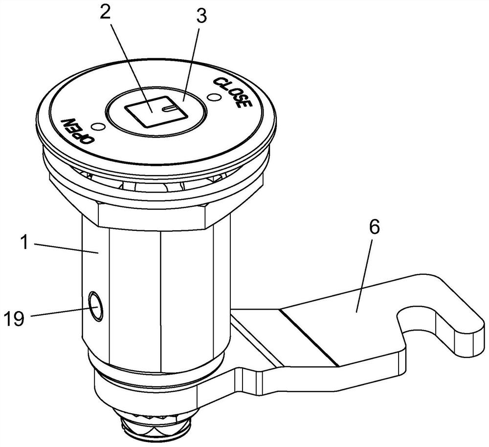
  • Tensioning lock with safety function
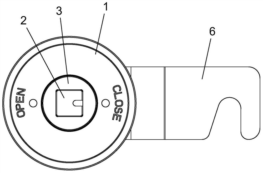
  • Tensioning lock with safety function
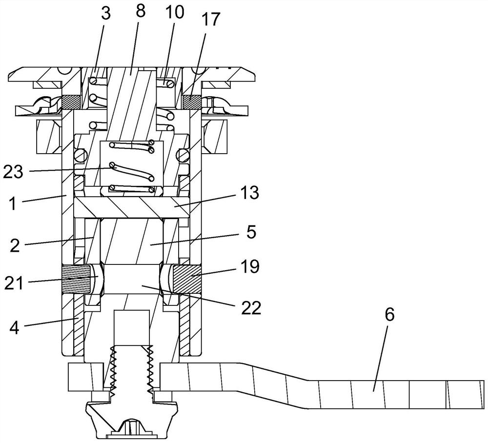
  • Tensioning lock with safety function

Examples


Embodiment

[0045] Embodiment: The following will clearly illustrate this case with drawings and detailed descriptions. After any person skilled in the art understands the embodiment of this case, he can change and modify it by the technology taught in this case without departing from the spirit of this case. with range.

[0046] The terminology used herein is for the purpose of describing particular embodiments only, and is not intended to be limiting of the present case. Singular forms such as "a", "the", "the", "this" and "the", as used herein, also include plural forms.

[0047] The terms “first” and “second” used herein do not refer to a sequence or order, nor are they used to limit the present application, but are only used to distinguish components or operations described with the same technical terms.

[0048] As used herein, "connection" or "positioning" can mean that two or more components or devices are in direct physical contact with each other, or that they are in indirect p...


PUM


Abstract

A tensioning lock with a safety function comprises a lock shell, a lock cylinder, a lock cylinder cover, a lock cylinder sleeve, a lock rod and a lock tongue. The lock cylinder is arranged in the lock shell in a penetrating mode and only rotates. An action part is arranged at the upper end of the lock cylinder in a protruding mode. The lock cylinder cover is arranged on the action part in a sleeving mode. The lock cylinder sleeve is arranged on the lock cylinder in a sleeving mode and fixedly arranged on the lock shell. The lock rod is arranged in the lock cylinder in a penetrating mode. The lower part of the lock rod is fixedly connected with the lock tongue. The tensioning lock further comprises a pin body. The pin body is horizontally arranged in the lock rod in a penetrating mode, and the end portion of the pin body outwards extends out of the outer side of the lock rod. The lock cylinder is provided with an inclined groove, the end portion of the pin body extends into the inclined groove, and when the lock cylinder rotates, the lock rod is driven to move in the vertical direction through cooperation of the pin body and the inclined groove. A long groove is formed in the periphery of the lock cylinder sleeve, the long groove is horizontally formed, and one end of the long groove is upwards connected with a vertical groove. The tensioning lock is ingenious in design, unlocking and locking operation is convenient, and the operation process is smooth; and meanwhile, tensioning of the tensioning lock is powerful during locking, and it can be guaranteed that the locking state of the tensioning lock is reliable and stable.

Description

technical field [0001] The invention relates to a lockset, in particular to a tension lock with safety function for industrial use in rail transit, wind power generation, communication equipment and other industries. The turning tongue of the lockset not only has a locking function but also has a tensioning function, and can be applied to door bodies, windows, cabinets and the like. Background technique [0002] On vehicles or equipment in rail transit, wind power generation, communication equipment and other industries, a large number of industrial locks are used to lock the door body or window. Chinese patent CN2549104Y discloses a patent for invention called "bolt retractable door lock". The patented door lock is composed of a lock case, an outer guide sleeve, an inner guide sleeve, a lock cylinder, a rotating shaft, a pin, a lock tongue and other parts. There is a set of spiral guide mechanism inside the lock case. The guide mechanism consists of an outer guide sleeve, ...

Claims


Application Information

Patent Timeline
Patent Type & Authority Applications(China)
IPC IPC(8): E05B15/10E05B15/00E05B15/12
CPCE05B15/00E05B15/10
Inventor 周发展王金平
Owner SUZHOU D SNAP TECH
Learn More