Reversing valve structure of hydraulic breaking hammer

A technology of hydraulic breaker and reversing valve, which is applied in the direction of fluid pressure actuation device, fluid pressure actuation system components, servo motor components, etc., and can solve problems such as mid-cylinder cavitation

Pending Publication Date: 2021-05-11
TAIZHOU BEILITE MASCH CO LTD
View PDF0 Cites 3 Cited by
  • Summary
  • Abstract
  • Description
  • Claims
  • Application Information

AI Technical Summary

Problems solved by technology

[0010] The purpose of the present invention is to solve the above-mentioned problems in the existing technology, and propose a reversing valve structur

Method used


Image

  • Reversing valve structure of hydraulic breaking hammer
  • Reversing valve structure of hydraulic breaking hammer
  • Reversing valve structure of hydraulic breaking hammer

Examples


Embodiment 1

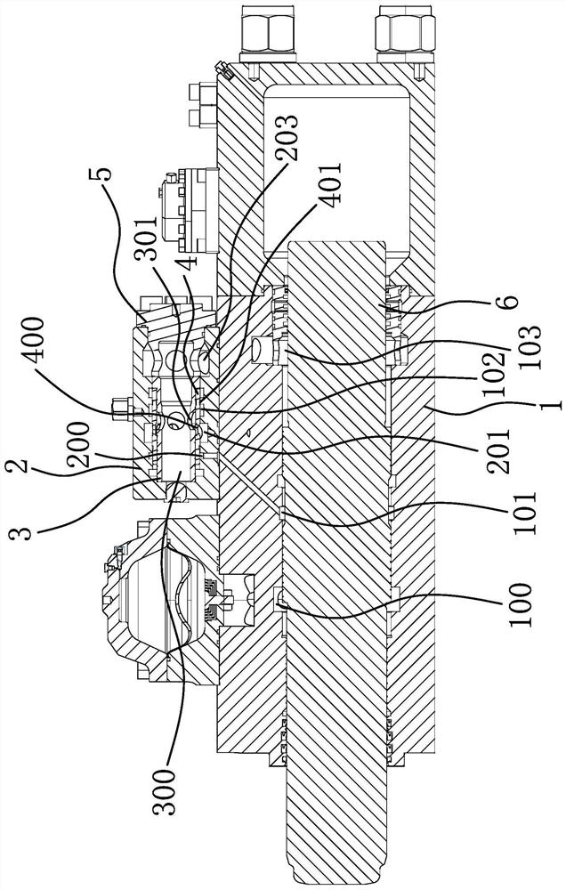
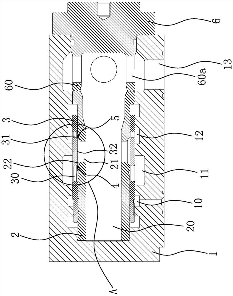
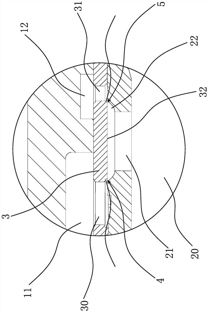
[0029] Such as figure 2 and image 3 As shown, the reversing valve structure of the hydraulic breaker includes a valve body 1, a valve core 2 arranged in the valve body 1, and a reversing valve 3 slidingly arranged between the valve body 1 and the valve core 2. The valve body 1 A reversing chamber 10, a high-pressure chamber 11 and a low-pressure chamber 12 are provided along the inner peripheral surface of the valve core. The valve core 2 has a high-low pressure switching chamber 20, and the middle part of the valve core 2 is provided with an oil hole 21 communicating with the high-low pressure switching chamber 20. , the reversing valve 3 has the oil hole 2 30 that can communicate with the high pressure chamber 11 and the oil hole 1 21, and the oil hole 3 31 that can communicate with the low pressure chamber 12 and the oil hole 1 21, and the inner peripheral surface of the reversing valve 3 is located at the oil hole 2 The position between 30 and oil hole 3 31 has a blocki...

Embodiment 2

[0034] The content of this embodiment is basically the same as that of the above-mentioned embodiment 1, the difference is that in this embodiment, an annular groove 22 is provided on the outer peripheral surface of the valve core 2, and an oil hole 21 is provided on the bottom surface of the groove 22. When the plugging part 32 moves to be opposite to the oil hole 1 21, the oil passage 1 4 communicates with the high-pressure chamber 11 and the groove 22, and the oil passage 2 5 communicates with the low-pressure chamber 12 and the groove 22, and the groove 22 is along the spool 2. The width in the axial direction is greater than the width of the blocking portion 32 in the axial direction of the valve core 2 .

Embodiment 3

[0036] The content of this embodiment is basically the same as that of the above-mentioned embodiment 1. The difference is that in this embodiment, the outer wall of the valve core 2 is provided with a through hole 1 and a through hole 2 along the radial direction. When one 21 is opposite, the through hole one communicates with the high pressure chamber 11 and the oil hole one 21, and the through hole two communicates with the low pressure chamber 12 and the oil hole one 21.


PUM


Abstract

The invention provides a reversing valve structure of a hydraulic breaking hammer, and belongs to the technical field of breaking hammers. The problem of cavitation of an existing middle cylinder body is solved. The reversing valve structure of the hydraulic breaking hammer comprises a valve body, a valve element arranged in the valve body and a reversing valve arranged between the valve body and the valve element in a sliding mode, wherein a reversing cavity, a high-pressure cavity and a low-pressure cavity are formed in the inner circumferential face of the valve body in the circumferential direction of the valve body, a high-low pressure switching cavity is formed in the valve element, and a first oil hole communicating with the high-low pressure switching cavity is formed in the middle of the valve element. The reversing valve is provided with a second oil hole capable of communicating with the high-pressure cavity with the first oil hole and a third oil hole capable of communicating with the low-pressure cavity with the first oil hole, and a blocking part is arranged at the position, between the second oil hole and the third oil hole, of the inner circumferential face of the reversing valve. When the plugging part moves to be right opposite to the first oil hole, the reversing valve structure further comprises an oil passing structure communicating the high-pressure cavity with the first oil hole or/and communicating the low-pressure cavity with the first oil hole. The structure solves the problem of cavitation of the middle cylinder body.

Description

technical field [0001] The invention belongs to the technical field of breaking hammers, in particular to a reversing valve structure of a hydraulic breaking hammer. Background technique [0002] The hydraulic breaker is a high-efficiency crushing tool that converts hydraulic energy into mechanical impact energy. It can effectively expand the host function as a load-bearing equipment and is widely used in railways, highways, mines, water conservancy, national defense projects and municipal construction projects. The breaker consists of a front cylinder, a middle cylinder, a rear cylinder, a drill rod, a piston, an accumulator and a reversing valve. The drill rod realizes the function of crushing. [0003] Such as figure 1 As shown, the middle cylinder body 1 has a front oil chamber 100, a high and low pressure conversion chamber 101 and a rear oil chamber 103 from left to right. The valve core 3 in the valve body 2, the reversing valve 4 arranged between the valve core 3 ...

Claims


Application Information

Patent Timeline
IPC IPC(8): F15B13/02F15B1/02F15B21/00F15B21/047
CPCF15B1/02F15B13/02F15B21/00F15B21/047
Inventor 林雨才蔡斌丰林志
Owner TAIZHOU BEILITE MASCH CO LTD
Why Eureka
Try Eureka