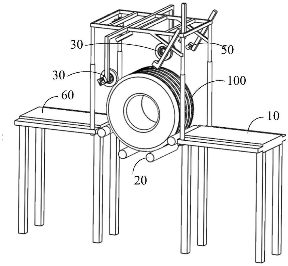
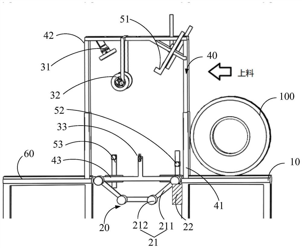
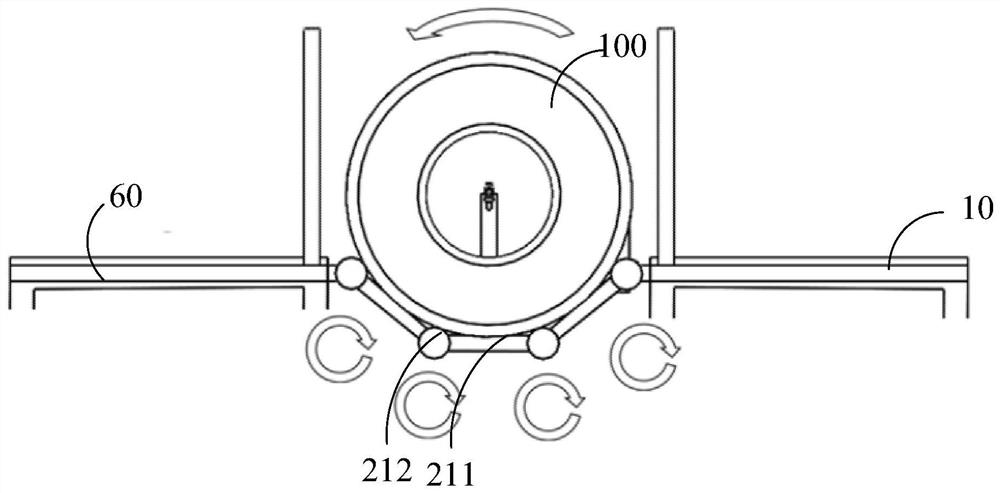
Tire flaw detection device

A defect detection and tire technology, applied in measuring devices, automobile tire testing, optical testing defects/defects, etc., can solve problems such as low efficiency and low accuracy, and achieve the effect of improving efficiency and accuracy

Pending Publication Date: 2021-06-22
创新奇智(上海)科技有限公司
View PDF0 Cites 0 Cited by
  • Summary
  • Abstract
  • Description
  • Claims
  • Application Information

AI Technical Summary

Problems solved by technology

Manual detection is inefficient and less accurate

Method used


Image

  • Tire flaw detection device
  • Tire flaw detection device
  • Tire flaw detection device

Examples


Embodiment Construction

[0041] The technical solutions in the embodiments of the present application will be clearly and completely described below in conjunction with the drawings in the embodiments of the present application.

[0042] In the description of this application, it should be noted that the orientation or positional relationship indicated by the terms "inner", "outer", etc. is based on the orientation or positional relationship shown in the drawings, or the usual placement of the application product when it is used. Orientation or positional relationship is only for the convenience of describing the present application and simplifying the description, and does not indicate or imply that the referred device or element must have a specific orientation, be constructed and operated in a specific orientation, and thus should not be construed as limiting the present application. Furthermore, in describing the present invention, it is to be understood that the terms "center", "longitudinal", "tr...


PUM


Abstract

The invention provides a tire flaw detection device which comprises a feeding table used for guiding a to-be-detected tire into a detection area; a bearing mechanism, arranged in the detection area, associated with the feeding table and used for bearing the tire guided into the detection area and driving the tire to rotate in the axial direction of the tire; a camera module, used for collecting images of the tire at multiple angles; a main control module, connected with the camera module and used for carrying out defect identification on the tire based on the image and generating a defect signal when a defect is detected; and a blanking table, associated with the bearing mechanism and used for sending out the detected tire.

Description

technical field [0001] The present application relates to the technical field of tire detection, in particular to a tire defect detection device. Background technique [0002] The tire industry is an important part of the downstream industry of the automobile manufacturing industry. Traditional tire production has the characteristics of large output, uneven quality and extensive industry. At this stage, the demand for precision tire quality inspection in high-end tire manufacturing is increasingly urgent. [0003] At present, the quality inspection method of most tire manufacturers is manual inspection. In the next process of tire production, one or more quality inspectors are placed. When a tire enters the inspection area, the inspector holds a flashlight or headlight and other lighting tools, and probes into the interior of the tire for flaw detection. Afterwards, manual inspections are performed on the outer sides, ground contact surfaces, and hub joints. Manual detect...

Claims


Application Information

Patent Timeline
IPC IPC(8): G01N21/88G01M17/02
CPCG01N21/8851G01M17/027G01N2021/8887
Inventor 汤寅航刁晓淳
Owner 创新奇智(上海)科技有限公司
Why Eureka
Try Eureka