Clamp

A fixture and component technology, applied in the direction of manufacturing tools, workpiece clamping devices, etc., can solve the problems of cylinder head rollover, difficult cylinder head clamping, waste of box space, etc.

Pending Publication Date: 2021-07-13
GUANGDONG ORIGINAL POINT INTELLIGENT TECH CO LTD
View PDF0 Cites 0 Cited by
  • Summary
  • Abstract
  • Description
  • Claims
  • Application Information

AI Technical Summary

Problems solved by technology

[0002] The shape of the outer surface of the cylinder head of different types of engines is different, and it is difficult to clamp the cylinder head from the cylinder head when it is stacked in the box. At present, in order to be able to clamp the cylinder head stacked in the box, it is necessary to make the cylinder head It is arranged at intervals, and there is a gap between the cylinder head and the inner wall of the box, so as to leave a space for the jaws to pick up. However, placing the cylinder head in this way will waste the space in the box, and the cylinder head is on the inner wall of the box and the cylinder on the same level. If the distance between the heads is large, it is easy to cause the cylinder head to roll over when transporting the cylinder head

Method used


Image

  • Clamp
  • Clamp
  • Clamp

Examples


Embodiment Construction

[0026] The idea, specific structure and technical effects of the present invention will be clearly and completely described below in conjunction with the embodiments and accompanying drawings, so as to fully understand the purpose, features and effects of the present invention. Apparently, the described embodiments are only some of the embodiments of the present invention, rather than all of them. Based on the embodiments of the present invention, other embodiments obtained by those skilled in the art without creative efforts belong to The protection scope of the present invention. In addition, all the connection / connection relationships mentioned in this article do not refer to the direct connection of components, but mean that a better connection structure can be formed by adding or reducing connection accessories according to specific implementation conditions. The various technical features in the invention can be combined interactively on the premise of not conflicting wi...


PUM


Abstract

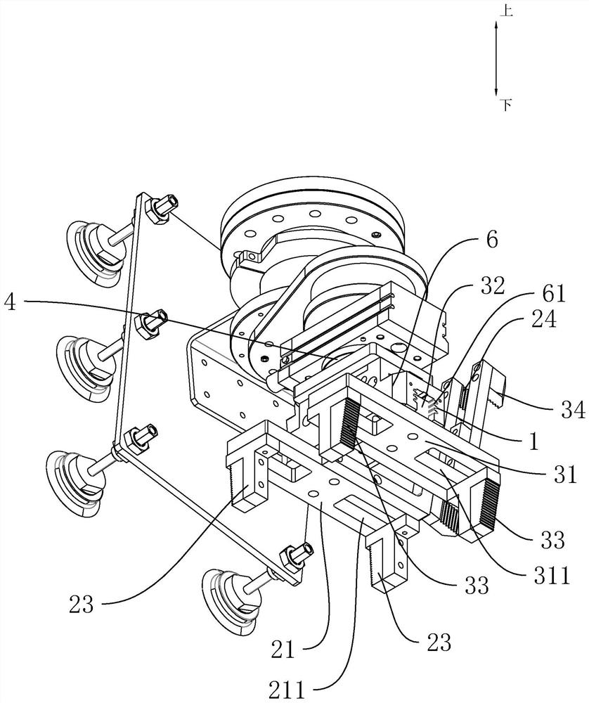
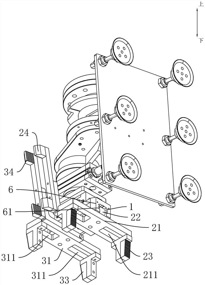
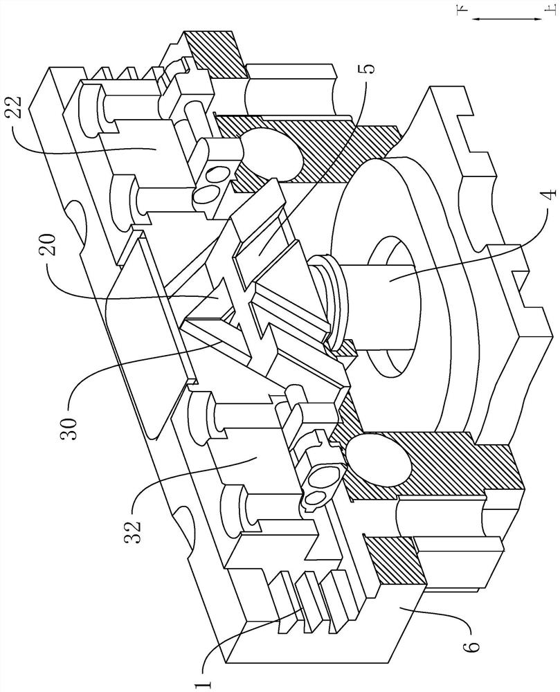
The invention relates to a clamp. The clamp comprises a base, a left sliding rail, a right sliding rail, a left outer supporting assembly, a right outer supporting assembly, a lifting device and a lifting block, the length of the left sliding rail and the length of the right sliding rail extend in the left-right direction, and the left sliding rail and the right sliding rail are arranged on the base; and the left outer supporting assembly is in sliding fit with the left and right sliding rails. The right outer supporting assembly is in sliding fit with the left and right sliding rails, and an open space is formed between the left outer supporting assembly and the right outer supporting assembly. The lifting device is arranged on the base; and the lifting device is in driving connection with the lifting block and drives the lifting block to move up and down in a reciprocating mode, the lifting block is in linkage connection with the left outer supporting assembly and the right outer supporting assembly, and the lifting block drives the left and right outer supporting assemblies to move away from each other or close to each other, so that the open space is enlarged or shrunk. The invention provides the clamp convenient for grabbing a cylinder cover.

Description

technical field [0001] The invention relates to the field of clamping devices, in particular to a clamp. Background technique [0002] The shape of the outer surface of the cylinder head of different types of engines is different, and it is difficult to clamp the cylinder head from the cylinder head when it is stacked in the box. At present, in order to be able to clamp the cylinder head stacked in the box, it is necessary to make the cylinder head It is arranged at intervals, and there is a gap between the cylinder head and the inner wall of the box, so as to leave a space for the jaws to pick up. However, placing the cylinder head in this way will waste the space in the box, and the cylinder head is on the inner wall of the box and the cylinder on the same level. If the distance between the heads is large, it is easy to cause the cylinder head to roll over when transporting the cylinder head. Contents of the invention [0003] The technical problem to be solved by the p...

Claims


Application Information

Patent Timeline
Patent Type & Authority Applications(China)
IPC IPC(8): B25B11/00
CPCB25B11/00
Inventor 曾超峰刘志峰张鹏飞黄永恒黎镇源彭胤荣
Owner GUANGDONG ORIGINAL POINT INTELLIGENT TECH CO LTD
Why Eureka
Try Eureka