Textile printing and dyeing equipment and application method thereof

A technology for printing and dyeing equipment and textiles, which is applied in the processing of textile materials, equipment configuration, textiles and papermaking, and textile materials processing. It can solve the problems of dyeing liquid waste and affecting dyeing effects, and achieve the effect of recycling

Inactive Publication Date: 2020-07-28
绍兴柯桥三杰纺织品有限公司
View PDF1 Cites 3 Cited by
  • Summary
  • Abstract
  • Description
  • Claims
  • Application Information

AI Technical Summary

Problems solved by technology

[0004] The purpose of the present invention is to solve the problem that because it is difficult to keep the fabric completely flat during the process of conveying the fabric, there are often wrinkles, so the surface of the fabric output from the dye solution is likely to have dye solution, especially more residues in the folds. The remaining dye solution will not only affect the dyeing effect, but also cause the waste of dye solution, and a textile printing and dyeing equipment and its use method are proposed

Method used


Image

  • Textile printing and dyeing equipment and application method thereof
  • Textile printing and dyeing equipment and application method thereof
  • Textile printing and dyeing equipment and application method thereof

Examples


Embodiment 1

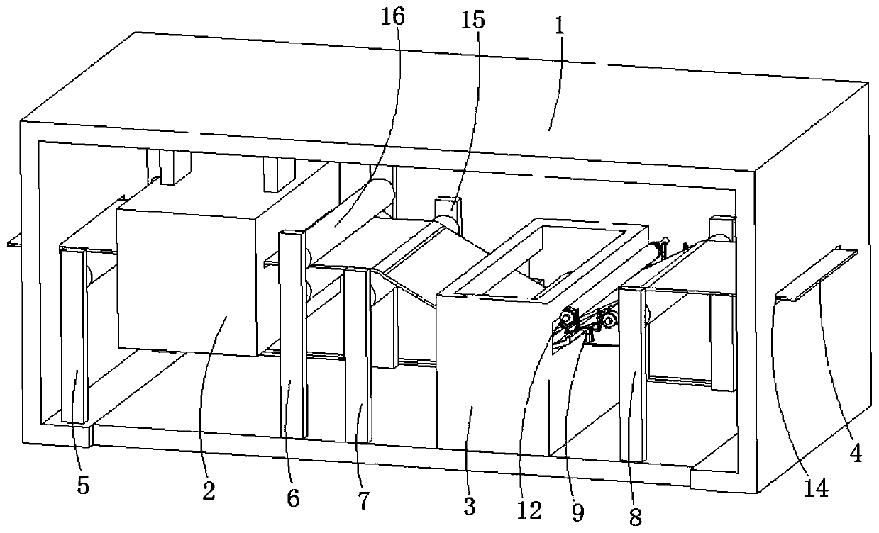
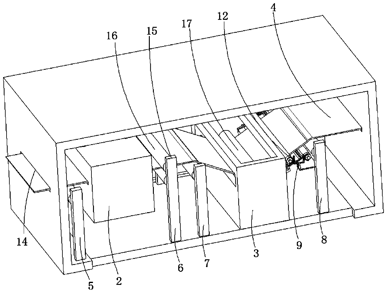
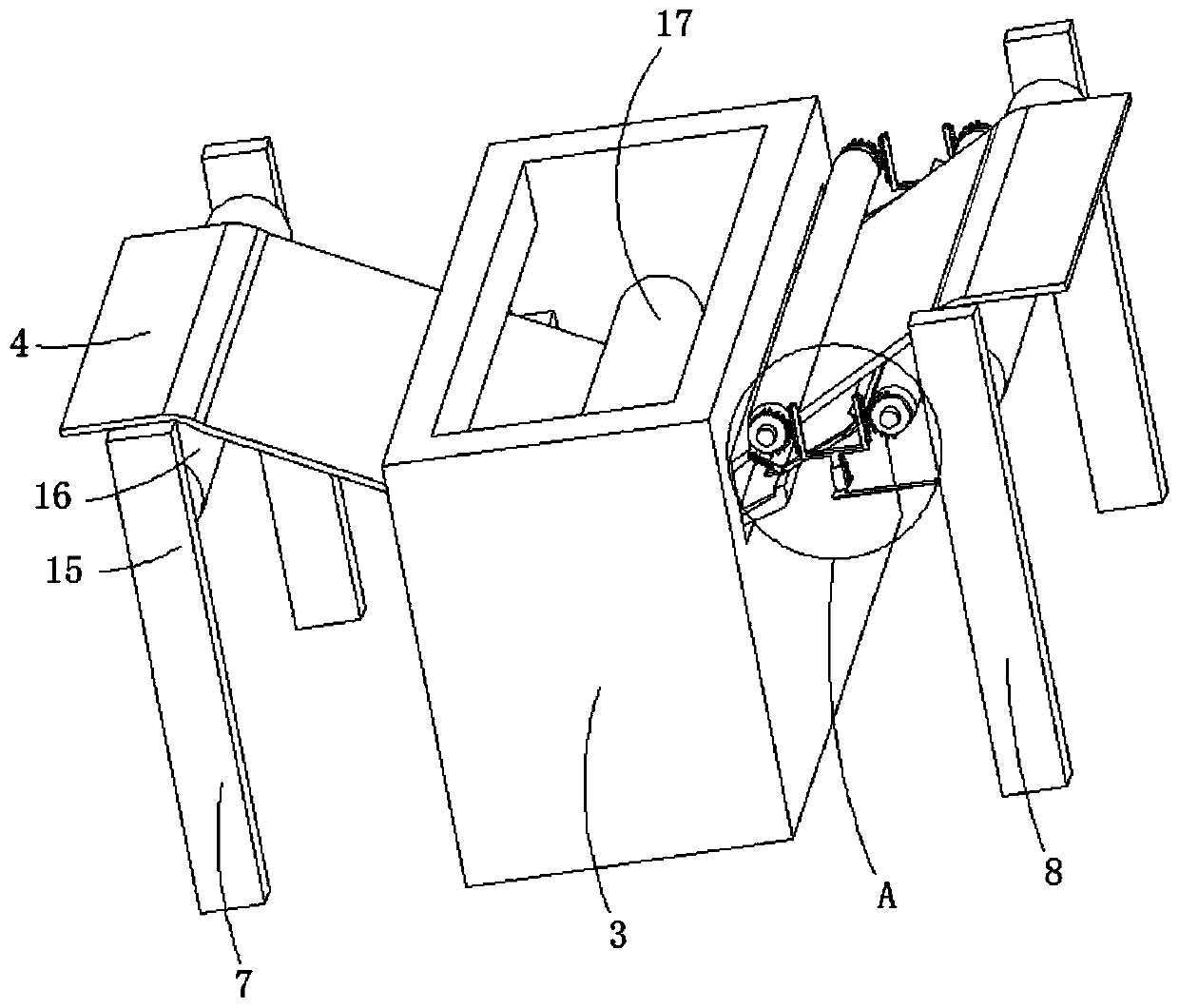
[0046] refer to Figure 1-9 , a kind of textile printing and dyeing equipment and using method thereof, comprising shell 1, drying box 2, printing and dyeing box 3, textile 4, drying box 2 is fixed on the front end top wall of shell 1, and printing and dyeing box 3 is fixed on shell On the bottom wall of the rear end of the body 1, it also includes a first guide roller shaft 5 and a second guide roller shaft 6 placed on both sides of the drying box 2, and a third guide roller shaft 7 and a second guide roller shaft placed on both sides of the printing and dyeing box 3 Four guide roller shafts 8, the side wall of the fourth guide roller shaft 8 is also fixedly provided with a winding mechanism 9, and the winding mechanism 9 includes:

[0047] The first winding roller shaft 9-1, the second winding roller shaft 9-2, the winding soft block 9-3, the recycling hopper 9-4, the driving mechanism 12, the collecting hopper 13, the first winding roller shaft 9- 1 and the second winding ...


PUM


Abstract

The invention discloses textile printing and dyeing equipment and an application method thereof, and belongs to the technical field of textile printing and dyeing equipment. The textile printing and dyeing equipment comprises a shell, a drying box, a printing and dyeing box and textiles. The drying box is fixedly arranged on the top wall of the front end of the shell, and the printing and dyeing box is fixedly arranged on the bottom wall of the rear end of the shell; a first guide roller shaft, a second guide roller shaft, a third guide roller shaft and a fourth guide roller shaft are furtherincluded, the first guide roller shaft and the second guide roller shaft are arranged on two sides of the drying box, and the third guide roller shaft and the fourth guide roller shaft are placed on two sides of the printing and dyeing box. A winding mechanism is further fixedly arranged on the side wall of the fourth guide roller shaft, and the winding mechanism comprises a first winding roller shaft and a second winding roller shaft. According to the textile printing and dyeing equipment and the application method thereof, the winding mechanism and a driving mechanism are arranged, the driving mechanism is used for driving the winding mechanism to work, the winding mechanism then tightly supports and squeezes the textiles through a winding soft block, while the textiles are combed and flattened, the residual dye liquor on the textiles is filtered out, and the filtered dye liquor can flows back to inside of the printing and dyeing box through a recycling hopper.

Description

technical field [0001] The invention relates to the technical field of textile printing and dyeing equipment, in particular to a textile printing and dyeing equipment and a method for using the same. Background technique [0002] Printing and dyeing is a combination of physical and chemical treatment of textiles, such as adding patterns and patterns to textiles, changing the color of textiles and related pre-treatment processes, etc., through physical or chemical changes between fuel and fibers , will make the fabric have a certain color and gloss. [0003] Printing and dyeing is an important process before fabric molding. At present, when dyeing textiles, the fabric is usually directly placed in the dyeing solution for dip-dyeing. For example, the patent application number is 201911137602.0, the application publication number is CN110791898A, and the invention name is a Patent for textile printing and dyeing equipment. In the printing and dyeing process disclosed by the a...

Claims


Application Information

Patent Timeline
Patent Type & Authority Applications(China)
IPC IPC(8): D06B3/10D06B23/20B65H18/10B65H18/26B65H23/34B65H20/02D06B15/08D06B15/00
CPCB65H18/10B65H18/26B65H20/02B65H23/34D06B3/10D06B15/005D06B15/085D06B23/20D06B2700/09D06B2700/36
Inventor 李军良
Owner 绍兴柯桥三杰纺织品有限公司
Why Eureka
Try Eureka