
Illuminating device for VR aviation cockpit

A technology for lighting devices and cockpits, which is applied in the field of lighting devices for VR aviation cockpits, can solve the problems that lighting devices do not have self-adjusting lighting direction and increase the flexibility of lighting adjustment of lighting devices, so as to increase the flexibility of lighting adjustment and adapt to The effect of strong scene ability and easy disassembly

Pending Publication Date: 2021-07-16
NANCHANG HANGKONG UNIVERSITY
View PDF0 Cites 0 Cited by
  • Summary
  • Abstract
  • Description
  • Claims
  • Application Information

AI Technical Summary

Problems solved by technology

[0006] Aiming at the technical problem that the current lighting device does not have the function of self-adjusting the lighting direction proposed in the background technology, the present invention uses a three-axis adjustment system to adjust the angle of the light source from the X\Y\Z three axes, so as to increase the number of lighting devices. The purpose of the light adjustment flexibility

Method used


Image

  • Illuminating device for VR aviation cockpit
  • Illuminating device for VR aviation cockpit

Examples


Embodiment Construction

[0028] The present invention will be further described in detail below in conjunction with the embodiments and the accompanying drawings, but the embodiments of the present invention are not limited thereto.

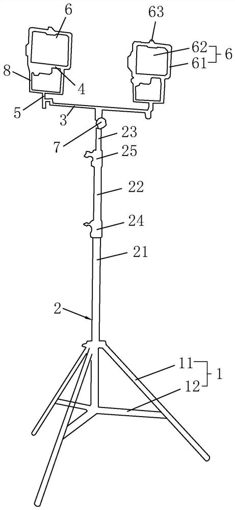
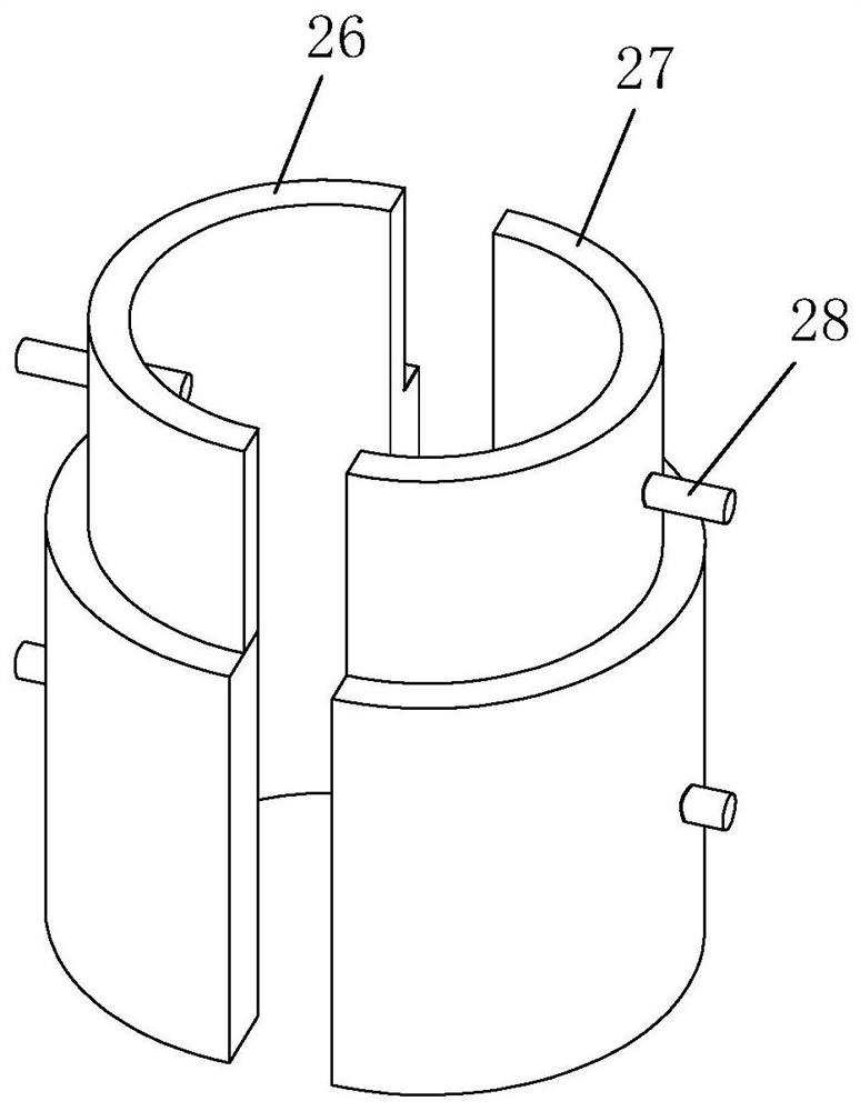
[0029] A lighting device for VR aviation cockpit, combined with figure 1 and figure 2 As shown, it includes a base 1, a support rod 2, an X-direction rotation shaft 3, a Y-direction rotation shaft 4, a Z-direction rotation shaft 5 and a light source 6. One end of the support rod 2 is installed on the base 1, and the support rod 2 The other end is rotationally connected to the middle part of the X-direction rotating shaft 3, and the first driving structure 7 is installed on the support rod 2, and the first driving structure 7 drives the X-direction rotating shaft 3 to rotate, and the two ends of the X-direction rotating shaft 3 are rotationally connected vertically. One end of the Z-direction rotating shaft 5 is provided, and the Z-direction rotating shaft 5 rotates aro...


PUM


Abstract

The invention relates to the technical field of lighting devices, and discloses a lighting device for a VR aviation cockpit, which solves the technical problem that the current lighting device does not have the function of automatically adjusting the lighting direction, and comprises a base, a support rod, an X-direction rotating shaft, a Y-direction rotating shaft, a Z-direction rotating shaft and a lamp source, the other end of the supporting rod is rotationally connected with the middle of the X-direction rotating shaft, the first driving structure drives the X-direction rotating shaft to rotate, the two ends of the X-direction rotating shaft are rotationally connected with one end of the Z-direction rotating shaft which is vertically arranged, the Z-direction rotating shaft rotates around the axis of the Z-direction rotating shaft, the Y-direction rotating shaft is rotationally installed on an installation frame, and the lamp source is installed on the Y-direction rotating shaft. And the X-direction rotating shaft, the Y-direction rotating shaft and the Z-direction rotating shaft are matched to rotate to adjust the irradiation direction of the lamp source. According to the technical scheme, the angle of the lamp source is adjusted from the X axis, the Y axis and the Z axis through the three-axis adjusting system, and therefore the purpose of improving the illumination adjusting flexibility of the lighting device is achieved.

Description

technical field [0001] The present invention relates to the technical field of lighting devices, more specifically, it relates to a lighting device for a VR aviation cockpit. Background technique [0002] VR (Virtual Reality), that is, virtual reality display technology, integrates computer graphics technology, computer simulation technology, sensor technology, display technology and other scientific technologies. Realistic immersion, with the ability to interact perfectly with the environment and help inspire ideas. The head-mounted virtual reality display device uses the head-mounted display to close the visual and auditory sense of people and the outside world, and guides the user to produce an immersive feeling. [0003] The principle of the virtual reality display device is: the close-up image generated by the display is pulled to the distance through the optical lens system to enlarge it, and it almost fills the human field of vision, thereby creating a sense of immer...

Claims


Application Information

Patent Timeline
IPC IPC(8): F21S6/00F21V21/14F21V21/22F21V21/36F21V15/01F21V19/00F21V23/00F21V17/12
CPCF21S6/005F21V21/14F21V21/22F21V21/36F21V15/01F21V19/00F21V23/009F21V17/12
Inventor 宋军
Owner NANCHANG HANGKONG UNIVERSITY
Learn More