New energy automobile intelligent identification charging interface

A new energy vehicle and charging interface technology, applied in electric vehicle charging technology, charging stations, electric vehicles, etc., can solve the problems of detachment of the charging gun from the charging equipment, exposure of the metal charging head, troubles, etc.

Inactive Publication Date: 2021-07-16
河南胜凡信息科技有限公司
View PDF0 Cites 2 Cited by
  • Summary
  • Abstract
  • Description
  • Claims
  • Application Information

AI Technical Summary

Problems solved by technology

[0008] In view of the above situation, in order to overcome the defects of the prior art, the present invention provides an intelligent identification charging interface for new energy vehicles, which effectively solves the phenomenon that t

Method used


Image

  • New energy automobile intelligent identification charging interface
  • New energy automobile intelligent identification charging interface
  • New energy automobile intelligent identification charging interface

Examples


Embodiment 1

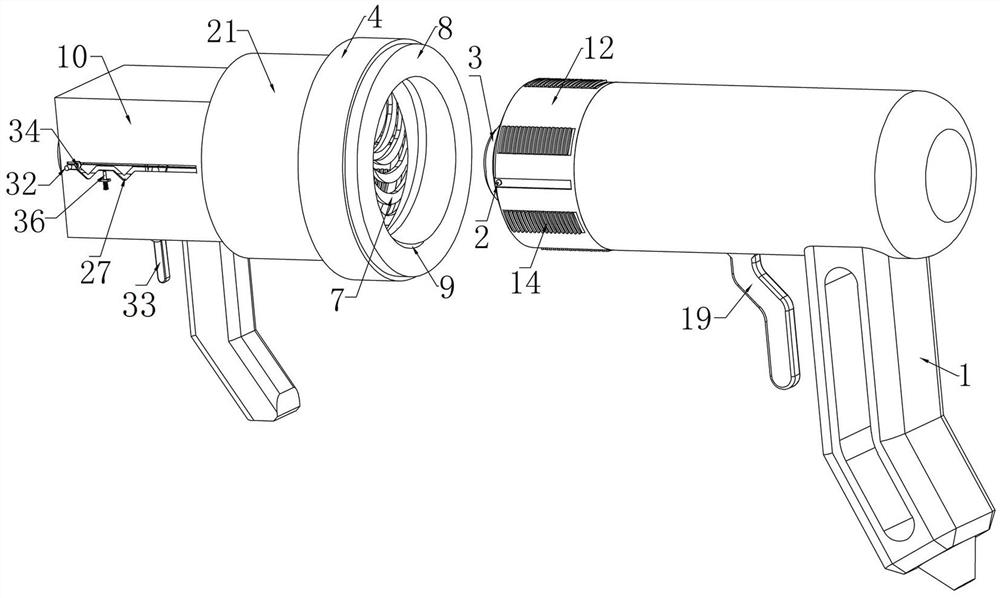
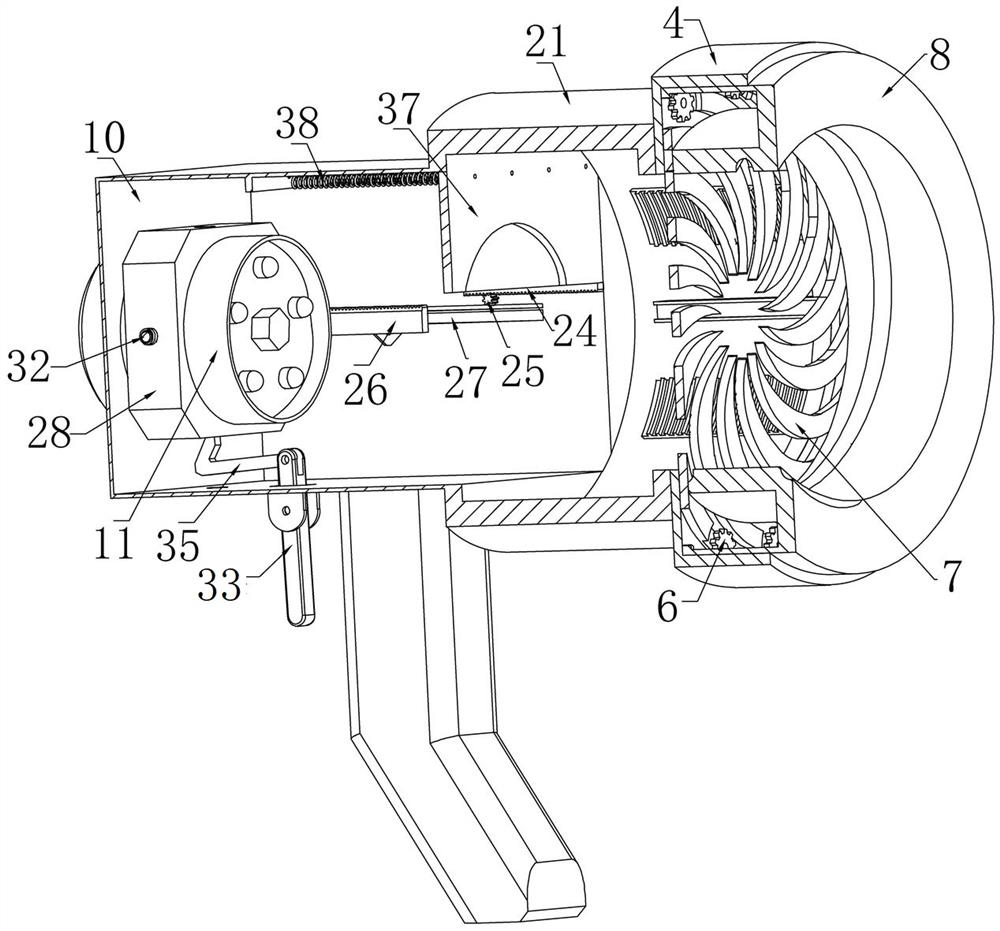
[0030] Embodiment one, such as Figure 1-2 As shown, the new energy vehicle intelligent identification charging interface includes a charging gun 1, the lower end of the right side of the charging gun 1 is fixedly connected to the charging handle, and the left end surface of the charging gun 1 is coaxially fixedly connected to the charging connector 3. The charging connector 3 is an existing new energy vehicle charging connector, and the charging handle is provided with a wire, one end of the wire is connected to the charging connector 3, and the other end is connected to the charging pile, and the charging gun 1 is detachable and installed On the charging pile, the front side of the charging gun 1 is fixedly connected with the driving ball 2 on the right side of the charging joint 3, and the left side of the charging joint 3 is provided with a fixed outer ring 4, and the fixed outer ring 4 The inner end on the left side is coaxially fixed and communicated with a carrier ring,...

Embodiment 2

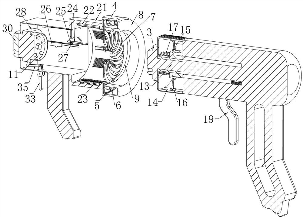
[0034] Embodiment two, on the basis of embodiment one, such as figure 2 As shown, the left end of the charging gun 1 is fixedly connected with an inner self-locking component, and the left end of the fixed outer ring 4 is fixedly connected with an outer self-locking component used in conjunction with the inner self-locking component. The left end of the outer self-locking component A charging box 10 is fixedly connected, and the charging box 10 is detachably installed on the car, and the charging interface assembly includes a charging interface 11 slidingly installed in the charging box 10 left and right;

[0035] When in use, when the new energy vehicle needs to be charged, manually remove the charging gun 1 from the charging pile, then hold the charging gun 1, and open the internal self-locking component at the same time, then insert the charging gun 1 horizontally into the drive ring 8 , when the charging connector 3 is fully inserted into the charging interface assembly, ...

Embodiment 3

[0036] Embodiment three, on the basis of embodiment one, such as Figure 4 As shown, the inner self-locking assembly includes a guide ring 12 coaxially fixedly connected to the left end of the charging gun 1. The circumferential surface of the guide ring 12 is uniformly penetrated with a plurality of limiting square holes, and each of the limiting square holes The left and right inner end faces of the hole are respectively parallel vertical slopes, and the front and rear sides of the guide ring 12 are respectively provided with limiting grooves, and the driving ball 2 is fixedly connected in the limiting grooves on the front side of the guide ring 12. At the upper end, the inside of the guide ring 12 is coaxially fixedly connected with a fixed column 13, and a clamping plate 14 is slidably installed in each limiting square hole on the guide ring 12, and each of the clamping plates 14 The left and right ends and the left and right inner end surfaces of each limiting square hole...


PUM


Abstract

The invention provides a new energy automobile intelligent identification charging interface. The problems that under the action of factors such as external force, a charging gun is separated from charging equipment, a metal charging head is exposed, safety accidents are caused, and corresponding troubles are brought to a user when the charging gun is damaged are effectively solved. A charging connector is coaxially and fixedly connected to the left end face of the charging gun, a driving ball located on the right side of the charging connector is fixedly connected to the front side face of the charging gun, a fixed outer ring is connected to the left side of the charging connector, and a gear ring is rotationally installed at the inner end of the left side of the fixed outer ring. A plurality of driving gears engaged with the gear ring are rotationally mounted at the inner end of the left side of the fixed outer ring. Through cooperative use of a driving ring, a threaded groove, the driving gear and a crescent plate, the interior of the driving ring can be blocked or opened, and then the situation that a metal charging head in an interface is touched unintentionally, and consequently safety accidents are caused is prevented.

Description

technical field [0001] The invention relates to the technical field of new energy vehicles, in particular to an intelligent identification charging interface for new energy vehicles. Background technique [0002] With the depletion of global oil and gas resources, people urgently need to find alternative new energy sources. Among them, electric power resources are a good green alternative energy source. With the country's strong support for new energy vehicles, the number of new energy vehicles is gradually increasing. What follows is the increase of corresponding supporting charging facilities. The supporting products, new energy vehicle charging piles, are also widely installed in public buildings, residential parking lots and charging stations. Ordinary new energy vehicle charging piles include those set on the ground with The power supply pile body, the charging gun electrically connected to the power supply pile body, and the supporting docking device installed inside t...

Claims


Application Information

Patent Timeline
IPC IPC(8): H01R13/44H01R13/639H01R13/502H01R24/00B60L53/16
CPCB60L53/16H01R13/44H01R13/502H01R13/639H01R24/00H01R2201/26Y02T10/70Y02T10/7072Y02T90/14
Inventor 李晓阳
Owner 河南胜凡信息科技有限公司
Why Eureka
Try Eureka