Outdoor electric power control cabinet based on Internet of Things

A technology of power control cabinet and Internet of Things, which is applied in the field of control cabinets, can solve the problems of increasing the damage of components in the power control cabinet and increasing fire, and achieves the effects of quick disassembly, avoidance of fire, and easy maintenance and replacement.

Active Publication Date:
View PDF7 Cites 0 Cited by
  • Summary
  • Abstract
  • Description
  • Claims
  • Application Information

AI Technical Summary

Problems solved by technology

[0002] The control cabinet is to assemble switchgear, measuring instruments, protective appliances and auxiliary equipment in a closed or semi-closed metal cabinet or on a screen width according to the requirements of electrical wiring. Its layout should meet the requirements of the normal operation of the power system. In the use of the control cabinet, the control cabinet will be monitored and operated with the help of the Internet of Things, and the control cabinet is often installed outdoors. The current power control cabinet is in use, in order to make the components in the power control cabinet work normally. The power control cabinet performs heat dissipation work. However, if the internal circuit of the control cabinet causes the components to catch fire due to factors such as short circuit, the heat dissipation route on the power control cabinet will increase the fire, thereby increasing the damage to the components in the power control cabinet. Therefore, It is necessary to design an outdoor power control cabinet based on the Internet of Things to solve the above problems

Method used


Image

  • Outdoor electric power control cabinet based on Internet of Things
  • Outdoor electric power control cabinet based on Internet of Things
  • Outdoor electric power control cabinet based on Internet of Things

Examples


Embodiment approach

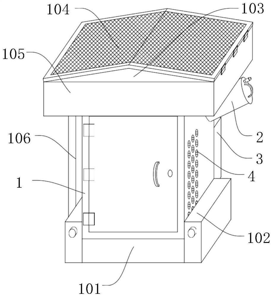
[0037] The specific implementation method is first to pass the L-shaped clamping plate 1021 on the auxiliary box 102 through the notch channel 1011 on the frame support frame 101, and then rotate the second two-way screw 1023 in the forward direction, because the second two-way screw 1023 and the two second The sleeve 1022 is threaded, so the rotation of the second two-way screw 1023 will cause the second sleeve 1022 to move outwards, and then under the action of the second supporting plate 1026, the moving plate 1025 will move downwards, and then the universal wheel 1024 will move downwards. Move down and contact with the ground, then continue to rotate the second two-way screw 1023, and make the auxiliary box 102 move upwards, and then make the L-shaped clamping plate 1021 move upwards, so that the L-shaped clamping plate 1021 is clamped with the notch through groove 1011, and simultaneously The above steps will cause the two auxiliary boxes 102 to be installed on the left an...


PUM


Abstract

The invention relates to the technical field of control cabinets, and particularly relates to an outdoor electric power control cabinet based on Internet of Things. The cabinet comprises a cabinet body, a bottle type tank body, a box body, a heat dissipation through groove, a speed reducer, a main chain wheel, an auxiliary chain wheel, first bidirectional screw rods, first sleeves, a driving motor, a barrier plate, first supporting plates, an electromagnetic valve and a connecting pipe. The driving motor and the speed reducer are arranged; under the action of the main chain wheel and the auxiliary chain wheel, the two first bidirectional screw rods synchronously rotate so that two first sleeves move outwards, the barrier plate moves forwards to a limit position under the action of two first supporting plates, and the heat dissipation through groove is blocked by the barrier plate so that gas circulation between the cabinet body and the outside is blocked; and fire is prevented from being bigger, the electromagnetic valve is started, the fire extinguishing agent in the bottle type tank body flows into the connecting pipe, and the fire extinguishing agent is sprayed into the closed cabinet body through the connecting pipe so that the fire extinguishing function is realized, the fire is prevented from being further increased, and the safety is high.

Description

technical field [0001] The invention is an outdoor power control cabinet based on the Internet of Things, belonging to the technical field of control cabinets. Background technique [0002] The control cabinet is to assemble switchgear, measuring instruments, protective appliances and auxiliary equipment in a closed or semi-closed metal cabinet or on a screen width according to the requirements of electrical wiring. The layout should meet the requirements of the normal operation of the power system. In the use of the control cabinet, the control cabinet will be monitored and operated with the help of the Internet of Things, and the control cabinet is often installed outdoors. The current power control cabinet is in use, in order to make the components in the power control cabinet work normally. The power control cabinet performs heat dissipation work. However, if the internal circuit of the control cabinet causes the components to catch fire due to factors such as short circ...

Claims


Application Information

Patent Timeline
Patent Type & Authority Applications(China)
IPC IPC(8): H02B1/30H02B1/28H02B1/52
CPCH02B1/30H02B1/28H02B1/52
Inventor 喻师师
Why Eureka
Try Eureka