Camera module and imaging method
A camera module, imaging surface technology, applied in image communication, TV, color TV components and other directions, can solve problems such as occupying space/volume
- Summary
- Abstract
- Description
- Claims
- Application Information
AI Technical Summary
Problems solved by technology
Method used
Image
Examples
Embodiment 1
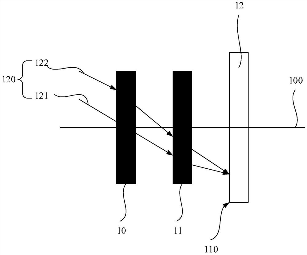
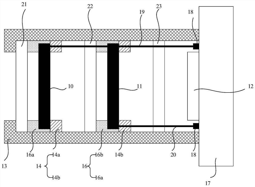
[0025] Please refer to figure 1 It is an illustrative intent for the camera module of the embodiment of the present invention. Such as figure 1 As shown, the camera module has a common optical axis 100 including: the first variable focus optical lens 10 and the second inclusive optical lens 11, the first roll of focus optical lens 10 focusing and The focal length of the second variable focus optical lens 11 can be adjusted, and the first varying optical lens 10 and the second varying focus optical lens 11 are stationary on the common optical axis 100 of the camera module. The first variable focus optical lens 10 is located on one side close to the object, the second variable focus optical lens 11 located on the end image surface, and the first inclusive optical lens 10 and the second inclusible optical The photocopy of the lens 11 has passed the common optical axis 100; the first variable focus optical lens 10 and the light rays of the second variable focus optical lens 11 have fi...
Embodiment 2
[0065] The main difference between the second embodiment of the present embodiment is, in the present embodiment, the first varylax optically lens is a self-zoom transmissive, and the second variable focus optical lens is a self-zoom mirror.
[0066] Specifically, such as Figure 8 Disted, and can be combined with reference Figures 1 to 7 The camera module comprises: the first variable focus optical lens 10 and the second inclination optical lens 11, the focal length of the first inclined optimal lens 10 and the focal length of the second variable focus optical lens 11 can be adjusted. The first inclined optimistic lens 10 and the second variable focus optical lens 11 are stationary on the common optical axis 100 of the camera module, and the first variable focus optical lens 10 is located on one side of the object. The second variable focus optical lens 11 is located on the end of the final imaging surface, and the core of the first inclined optimistic lens 10 and the second varia...
Embodiment 3
[0077] The main difference of the first embodiment and the first embodiment is that in the present embodiment, the first variable focus optical lens is a self-zoom mirror, and the second variable focus optical lens is a self-zoom transmission mirror.
[0078] Specifically, such as Figure 9 Disted, and can be combined with reference Figure 1 to 8 The camera module comprises: the first variable focus optical lens 10 and the second inclination optical lens 11, the focal length of the first inclined optimal lens 10 and the focal length of the second variable focus optical lens 11 can be adjusted. The first inclined optimistic lens 10 and the second variable focus optical lens 11 are stationary on the common optical axis 100 of the camera module, and the first variable focus optical lens 10 is located on one side of the object. The second variable focus optical lens 11 is located on the end of the final imaging surface, and the core of the first inclined optimistic lens 10 and the seco...
PUM
 Abstract
Description
Claims
Application Information
 - R&D
- Intellectual Property
- Life Sciences
- Materials
- Tech Scout
- Unparalleled Data Quality
- Higher Quality Content
- 60% Fewer Hallucinations
Browse by: Latest US Patents, China's latest patents, Technical Efficacy Thesaurus, Application Domain, Technology Topic, Popular Technical Reports.
© 2025 PatSnap. All rights reserved.Legal|Privacy policy|Modern Slavery Act Transparency Statement|Sitemap|About US| Contact US: help@patsnap.com


