Electric control optical zoom system

A technology of optics and multiples, applied in optics, optical components, instruments, etc., to achieve the effect of improving work efficiency, improving zoom precision, and high precision

Pending Publication Date: 2022-07-19
桂林方天光学仪器有限公司 +1
View PDF0 Cites 0 Cited by
  • Summary
  • Abstract
  • Description
  • Claims
  • Application Information

AI Technical Summary

Problems solved by technology

[0003] In view of this, the present invention proposes an electric control optical zoom system, which aims to solve the problem of positioning the rotation angle of the lens to eliminate the error of the transmission system, thereby precisely controlling the DC geared motor to improve the zoom accuracy of the lens

Method used


Image

  • Electric control optical zoom system
  • Electric control optical zoom system
  • Electric control optical zoom system

Examples


Embodiment Construction

[0060] Exemplary embodiments of the present disclosure will be described in more detail below with reference to the accompanying drawings. While exemplary embodiments of the present disclosure are shown in the drawings, it should be understood that the present disclosure may be embodied in various forms and should not be limited by the embodiments set forth herein. Rather, these embodiments are provided so that the present disclosure will be more thoroughly understood, and will fully convey the scope of the present disclosure to those skilled in the art. It should be noted that the embodiments of the present invention and the features of the embodiments may be combined with each other under the condition of no conflict. The present invention will be described in detail below with reference to the accompanying drawings and in conjunction with the embodiments.

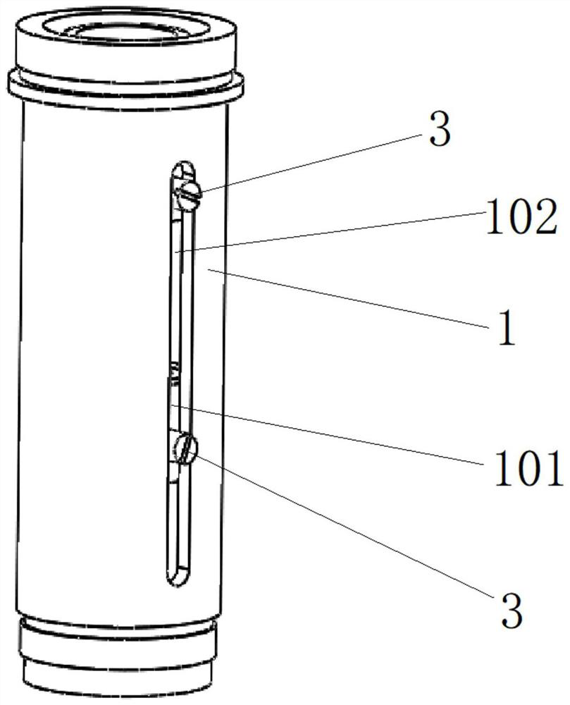
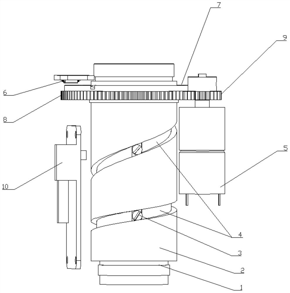
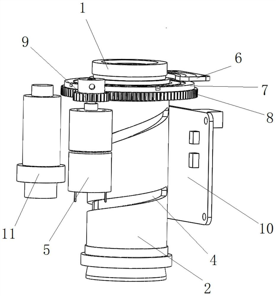
[0061] see Figure 1-5 As shown, this embodiment provides an electrically controlled optical zoom system, including ...


PUM


Abstract

The invention provides an electric control optical zoom system which comprises a lens guide cylinder, two sliding lenses arranged in the lens guide cylinder, a lens cam cylinder sleeving the outer side of the lens guide cylinder, a driven gear sleeving the outer side wall of the upper end of the lens cam cylinder, and an annular magnetic grid sleeving the outer side of the upper end of the lens cam cylinder. The magnetic induction sensor is arranged on the upper side of the annular magnetic grid, the direct-current gear motor is arranged on one side of the lens cam cylinder, the control circuit board is connected with the magnetic induction sensor and the direct-current gear motor, the direct-current gear motor drives the driving gear, the driven gear and the lens cam cylinder to rotate, and zooming of the lens is achieved. The rotation angle of the lens is positioned through the magnetic grid and the magnetic induction sensor which are annularly arranged, errors of a transmission system are eliminated, meanwhile, the precision of the magnetic grid and the magnetic induction sensor is extremely high, and the zoom precision of the lens can be effectively improved.

Description

technical field [0001] The invention relates to the technical field of optical measuring instruments, in particular to an electric control optical zoom system. Background technique [0002] At present, in the field of optical measuring instruments, the automatic zooming of the lens is generally driven by the motor to drive the gear, and the cam groove of the lens is driven to rotate through the gear transmission system to realize the zooming. The encoder is installed at the motor end as the feedback system. The gap error of the encoder is not high, and the resolution accuracy of the encoder is not high, resulting in low zoom accuracy; another solution is to use a linear magnetic grid, and the lens moves along the guide rail. The design is inherently insufficient, and there is serious stray light, which affects the imaging quality. SUMMARY OF THE INVENTION [0003] In view of this, the present invention proposes an electronically controlled optical zoom system, which aims ...

Claims


Application Information

Patent Timeline
Patent Type & Authority Applications(China)
IPC IPC(8): G02B7/09
CPCG02B7/09
Inventor 李沛任学庆
Owner 桂林方天光学仪器有限公司
Why Eureka
Try Eureka