AI technical title is built by Patsnap AI team. It summarizes the technical point description of the patent document.
An imaging module and imaging technology, applied in image communication, TV, color TV parts, etc.
Active Publication Date: 2022-07-12
NINGBO SEMICON INT CORP
View PDF5 Cites 0 Cited by
Summary
Abstract
Description
Claims
Application Information
AI Technical Summary
This helps you quickly interpret patents by identifying the three key elements:
Problems solved by technology
Method used
Benefits of technology
Problems solved by technology
[0004] The object of the present invention is to provide an imaging module and its manufacturing method, which can solve the problem of the lateral movement of the moved element
Method used
Image
Click on the blue label to locate the original text in one second.
Reading with bidirectional positioning of images and text.
Examples
Embodiment 1
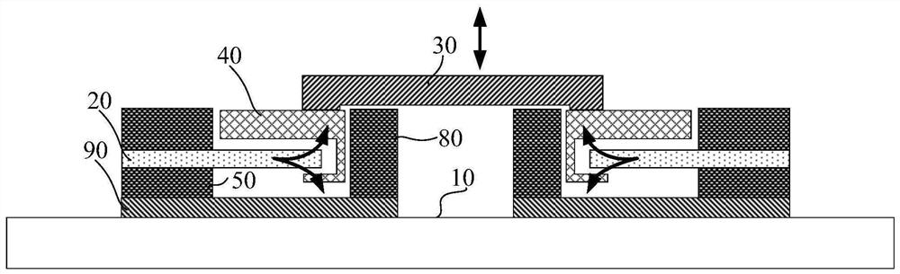
[0046] like figure 1 As shown, this embodiment provides an imaging module, including:
[0047] The moved element 30, the moved element 30 includes a lens group, an imaging sensor element, an aperture or a lens sheet;
[0048] a lifter connected to the surface of the moved element 30;
[0049] The lifter includes: a limit device, a limit slot 40, a piezoelectric element 20 and an external signal connection end,
[0050] The limiting device includes a base 90, a support block 50 and a positioning block 80 located on the base 90, the base 90, the support block 50 and the positioning block 80 enclose a space, the piezoelectric element 20 and the limiting slot 40 In the space, the positioning block 80 is located around the limiting groove 40;
[0051] the limiting groove 40 is fixedly connected with the surface of the moved element 30;
[0052]The piezoelectric element 20 includes a movable end and a fixed end, the fixed end is fixed on the support block 50 , the movable end ex...
Embodiment 2
[0087] A manufacturing method of an imaging module, characterized in that the moved element 30 includes a lens group, an imaging sensor element, an aperture or a lens sheet, and the method includes:
[0088] provide a base;
[0089] A lifter is formed on the base, and the lifter includes: a limiting device, a limiting slot 40 and a piezoelectric element 20 , the limiting device includes a base 90 , and a support block 50 and a positioning block located on the base 90 80, the base 90, the support block 50 and the positioning block 80 enclose a space, the piezoelectric element 20 and the limit slot 40 are located in the space, and the positioning block 80 is located around the limit slot 40;
[0090] The limiting groove 40 is fixedly connected with the surface of the moved element 30;
[0091] The piezoelectric element 20 includes a movable end and a fixed end, the fixed end is fixed on the support block 50, and the movable end extends into the limiting groove 40;
[0092] The...
PUM
Abstract
The invention provides an imaging module and a manufacturing method thereof. A piezoelectric element supports and connects a moved element, a limit groove is provided on the surface of the moved element, and a fixed end of the piezoelectric element is fixed to a support block. The movable end extends into the limit slot, the limit slot provides a moving space for the movable end, and the limit device includes a base, a support block and a positioning block located on the base, the base, the support block and the positioning block to enclose a space, the piezoelectric element and the limit slot are located in the space, and the positioning block is located around the limit slot; the limit slot is arranged in the space of the limit device, and is limited by the limit device. Under the action of the piezoelectric element, the limiting groove can only move up and down, thereby solving the problem of lateral movement of the moved element.
Description
technical field [0001] The invention relates to the technical field of motion control, and in particular, to an imaging module and a manufacturing method thereof. Background technique [0002] In some electronic terminals, it is usually necessary to make some of the components translate, vertically move or tilt, so as to realize some special functions. For example, in various electronic terminals such as cameras, cameras and mobile phones with lens modules, the movable lens or image sensor is usually driven by a driving mechanism such as a VCM motor (Voice CoilActuator / Voice Coil Motor, voice coil motor). , displaced in the optical axis direction to focus or zoom, or displaced in the direction perpendicular to the optical axis direction to prevent optical shake. However, unlike traditional SLR cameras, it is a huge engineering challenge to implement this function in electronic terminals such as mobile phones, miniature cameras, and cameras with small space and volume. Mor...
Claims
Application Information
Patent Timeline
Application Date:The date an application was filed.
Publication Date:The date a patent or application was officially published.
First Publication Date:The earliest publication date of a patent with the same application number.
Issue Date:Publication date of the patent grant document.
PCT Entry Date:The Entry date of PCT National Phase.
Estimated Expiry Date:The statutory expiry date of a patent right according to the Patent Law, and it is the longest term of protection that the patent right can achieve without the termination of the patent right due to other reasons(Term extension factor has been taken into account ).
Invalid Date:Actual expiry date is based on effective date or publication date of legal transaction data of invalid patent.

