Imaging module and its manufacturing method

An imaging module and imaging technology, applied in image communication, TV, color TV parts, etc.

Active Publication Date: 2022-07-12
NINGBO SEMICON INT CORP
View PDF4 Cites 0 Cited by
  • Summary
  • Abstract
  • Description
  • Claims
  • Application Information

AI Technical Summary

Problems solved by technology

[0004] The purpose of the present invention is to provide an imaging module and its manufacturing method to solve the problem of lateral movement of the moved element

Method used


Image

  • Imaging module and its manufacturing method
  • Imaging module and its manufacturing method
  • Imaging module and its manufacturing method

Examples


Embodiment 1

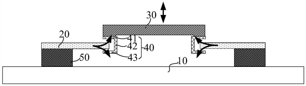
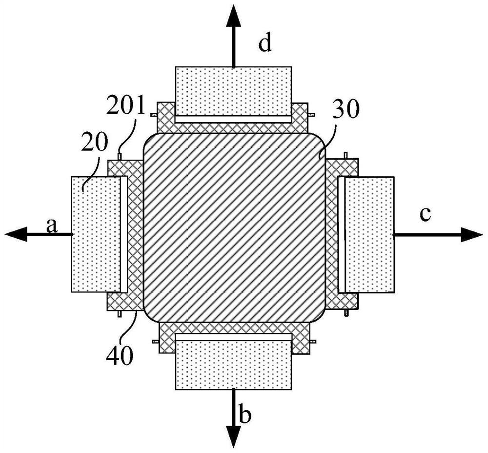
[0043] like figure 1 , figure 2 and image 3 As shown, this embodiment provides an imaging module, including:

[0044] The moved element 30, the moved element 30 includes a lens group, an imaging sensor element, an aperture or a lens sheet;

[0045] At least two lifters connected to the surface of the moved element 30, at least one group of adjacent two lifters intersect along the extension line of the first direction; image 3 As shown, the lifter in the a direction is a group with the b direction or the lifter in the a direction and the lifter in the c direction are a group,

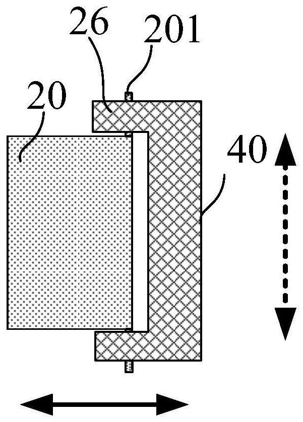
[0046]The lifter includes: a limit slot 40 , a piezoelectric element 20 , a support block 50 and a first external signal connection end, the limit slot 40 is fixedly connected to the surface of the moved element 30 ; the piezoelectric element 20 includes a movable end and a fixed end, the fixed end is fixed on the support block 50, and the movable end extends into the limit slot 40, and the limit ...

Embodiment 2

[0075] The difference between this embodiment and the above-mentioned embodiment is that the lateral movement of the moved element 30 is restricted by the sleeve 100 , so that the moved element 30 can only move vertically upward or downward.

[0076] like Figure 7a and 7b As shown, the imaging module further includes a sleeve 100, the sleeve 100 has a side wall, the plane where the moved element 30 is located is perpendicular to the side wall of the sleeve 100; the side wall is provided with a limit arm 101, The limit arms 101 are circumferentially distributed around the side wall of the moved element 30 , and the limit arms 101 and the side wall of the moved element 30 have a gap. like Figure 7a The limiting arm 101 is arranged on the side wall, and the side wall restricts the moved element 30 to only move up and down, but cannot move left and right back and forth. The shape of the side wall of the sleeve 100 can also be as follows Figure 7b As shown, the side wall con...

Embodiment 3

[0079] The difference between this embodiment and the above-mentioned embodiment is that an initial positioning device is provided, and the initial positioning device sets an initial position for the limit groove when the piezoelectric element is not energized, so as to facilitate assembly. After the limit groove is lifted, the initial positioning device no longer restricts the limit groove, thereby reducing the resistance of the limit groove to move.

[0080] like Figure 9 As shown, the lifter further includes: an initial positioning device, the initial positioning device includes: a base 90 and a positioning block 80 located on the base, the support block 50 is located on the base 90, and the positioning blocks 80 are distributed on the limit around bit slot 40 . The initial positioning device is used to set the initial placement position of the limit slot 40, that is, the position when the piezoelectric element 20 is not energized, and after the piezoelectric element 20 i...


PUM


Abstract

The invention provides an imaging module and a manufacturing method thereof. A piezoelectric element supports and connects a moved element, a limit groove is provided on the surface of the moved element, and a fixed end of the piezoelectric element is fixed to a support block. The movable end extends into the limit slot, the limit slot provides a moving space for the movable end, and the piezoelectric element is energized by using the external signal connection end electrically connected with the piezoelectric element, so that the piezoelectric element is energized. The movable end of the piezoelectric element is warped upward or downward relative to the fixed end to move the moved element. Blocks are arranged on both sides of the movable end of the piezoelectric element, and at least two adjacent lifts are arranged. In the process of lifting the moved element by the lifter, due to the included angle between the adjacent lifters, the set stops limit the movement of each other in the lateral direction, which solves the problem of the lateral movement of the moved element.

Description

technical field [0001] The invention relates to the technical field of motion control, and in particular, to an imaging module and a manufacturing method thereof. Background technique [0002] In some electronic terminals, it is usually necessary to make some of the components translate, vertically move or tilt, so as to realize some special functions. For example, in various electronic terminals such as cameras, cameras and mobile phones with lens modules, the movable lens or image sensor is usually driven by a driving mechanism such as a VCM motor (Voice Coil Actuator / Voice Coil Motor, voice coil motor). , displaced in the optical axis direction to focus or zoom, or displaced in the direction perpendicular to the optical axis direction to prevent optical shake. However, unlike traditional SLR cameras, it is a huge engineering challenge to implement this function in electronic terminals such as mobile phones, miniature cameras, and cameras with small space and volume. Mor...

Claims


Application Information

Patent Timeline
Patent Type & Authority Patents(China)
IPC IPC(8): H04N5/225
CPCH04N23/54H04N23/55
Inventor 桂珞
Owner NINGBO SEMICON INT CORP
Why Eureka
Try Eureka