
Multifunctional clamp with pressure sensor, control method and workpiece clamping device

A technology of a pressure sensor and a control method, which is applied in the direction of workpiece clamping devices, measuring devices, force/torque/power measuring instruments, etc., and can solve problems such as inability to measure the clamping force, failure to find the fixture device for the workpiece, and inability to use it flexibly. Achieve the effects of strong overall structural stability, simple maintenance methods, and long service life

Active Publication Date: 2021-07-23
OCEAN UNIV OF CHINA
View PDF7 Cites 0 Cited by
  • Summary
  • Abstract
  • Description
  • Claims
  • Application Information

AI Technical Summary

Problems solved by technology

[0005] (1) The function of the existing fixture is relatively single, and the holding position and method are fixed, which cannot be used flexibly
[0006] (2) The existing fixture device is often not stable enough during use, and it is easy to generate disturbance during use
[0007] (3) The size of the existing fixtures is mostly a standard fixed size, and the workpiece cannot find a fixture device corresponding to the appropriate size
[0008] (4) The materials of the existing fixture devices are mostly cast iron materials, which are prone to breakage during use, and are difficult to repair if damaged during use
[0009] (5) For accurate experiments, the traditional fixture system cannot measure the clamping force, so as to quantitatively describe the clamping degree

Method used


Image

  • Multifunctional clamp with pressure sensor, control method and workpiece clamping device
  • Multifunctional clamp with pressure sensor, control method and workpiece clamping device
  • Multifunctional clamp with pressure sensor, control method and workpiece clamping device

Examples


Embodiment 1

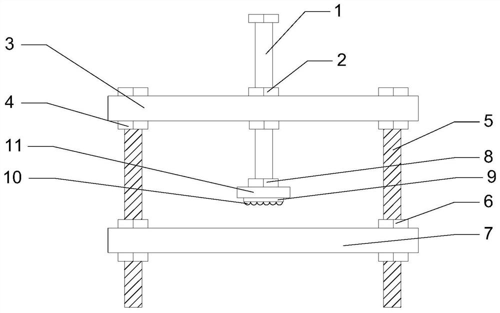
[0045] Such as figure 1 As shown, the multifunctional clamp with pressure sensor provided by the embodiment of the present invention is a multifunctional clamp in the form of a gantry clamp, including: a force applying bolt 1, a force applying screw fixing nut 2, an upper splint 3, and a fixing nut 4 on the support bolt , support bolt 5, support bolt lower fixing nut 6, lower splint (arc plate) 7, pressure sensor fixing nut 8, plane bearing slotted square 9, bearing ball 10 and pressure sensor 11. The force applying bolt 1 is fixed on the upper middle position of the upper splint 3 through the force applying screw fixing nut 2, and the lower end of the force applying bolt 1 is fixed with a pressure sensor fixing nut 8 through threads, and the pressure sensor fixing nut 8 is connected with the pressure sensor 11 and the flat bearing slotted square 9 are connected, and the plane bearing grooved block 9 is provided with bearing balls 10. The two ends of the upper splint 3 are pr...

Embodiment 2

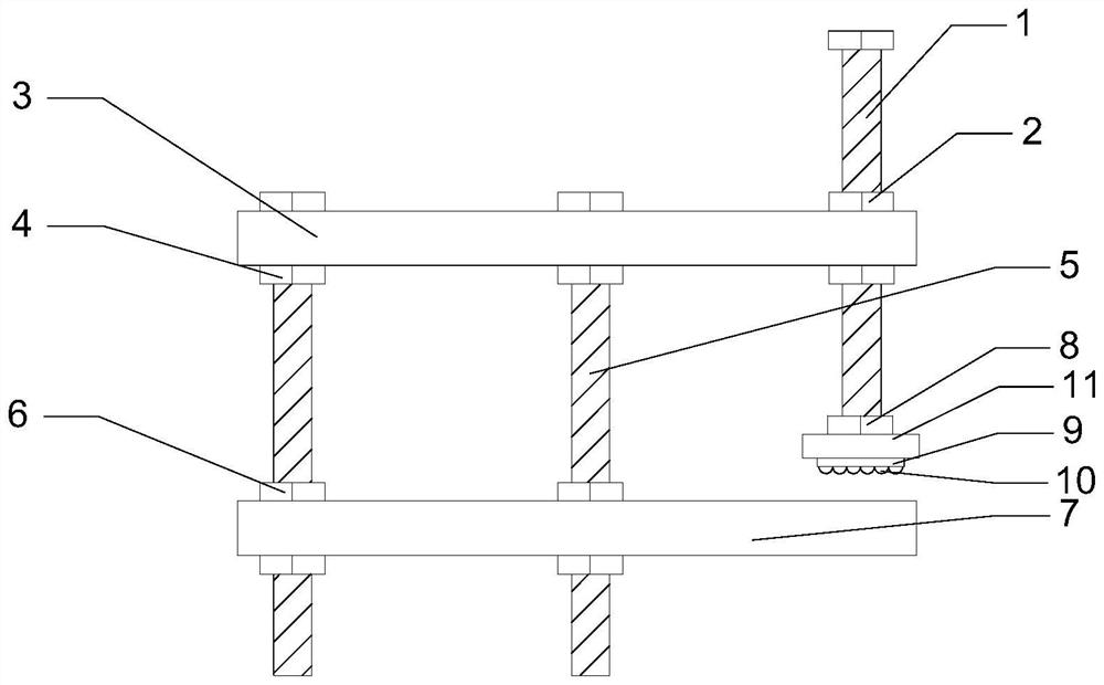
[0048] Such as figure 2 As shown, the embodiment of the present invention provides a multifunctional clamp with a pressure sensor in the form of an I-shaped clamp with a multifunctional clamp. The force applying bolt 1 is fixed on both ends of the upper splint 3 through the force applying screw fixing nut 2, the middle position of the upper splint 3 is screwed with a supporting bolt 5 through a threaded hole, and is fixed by the fixing nut 4 on the supporting bolt 5, and the lower end of the supporting bolt 5 passes through The fixing nut 6 under the support bolt is fixed with the lower splint 7 .

[0049] First, assemble the upper and lower splints with the middle support bolts, and fix the support bolts with the upper and lower nuts. The distance between the two splints is the maximum depth that the clamp can hold; then assemble and connect two force-applying bolts in the holes on both sides; Finally, the plane bearing and the pressure sensor are installed on the end of th...

Embodiment 3

[0051] Such as image 3 As shown, the multifunctional clamp with pressure sensor provided by the embodiment of the present invention is a C-shaped clamp form of a multifunctional clamp, and the force applying bolt 1 is screwed to one end of the upper splint 3 through a threaded hole, and the nut is fixed by the force applying screw 2 for fastening. One end of the upper splint 3 is screwed with two support bolts 5 through threaded holes, and is fastened by the fixing nut 4 on the support bolts. The lower ends of the two supporting bolts 5 are respectively screwed on the lower splint 7 through threaded holes, and fixed by the lower fixing nuts 6 of the supporting bolts.

[0052] First, assemble the upper and lower bolts with the two supporting bolts. The fixed positions of the two supporting bolts are in the two adjacent turning holes on one side of the splint. The distance between the two splints is the maximum depth that the clamp can hold. The support bolts are fixed, and t...


PUM


Abstract

The invention belongs to the technical field of constraint clamps, and discloses a multifunctional clamp with a pressure sensor, a control method and a workpiece clamping device. The multifunctional clamp with the pressure sensor is provided with a clamping plate used for supporting a workpiece, a force applying structure used for applying clamping force to the workpiece, a pressure sensor used for monitoring and measuring the clamping force, and a supporting structure providing a supporting effect for the whole clamp. According to the multifunctional clamp with the pressure sensor, the clamping position and mode are flexible, assembling deformation is carried out according to the clamping position requirement, and a gantry type clamp, a C type clamp and an I type clamp are formed to meet the requirement for different clamping positions of different workpieces; a lower clamping plate can be replaced by an arc plate, so that a cylindrical workpiece is clamped and fixed; a force application bolt can provide clamping force higher and more stable than the clamping force of a traditional clamp, and the overall structure is high in stability; the maintenance method in the using process is simple, and the service life is long; and meanwhile, the force applying structure is provided with the pressure sensor, the value of the clamping force of the clamp can be accurately measured, and the clamp can be used for some situations with specific requirements for the clamping force.

Description

technical field [0001] The invention belongs to the technical field of constraint fixtures, and in particular relates to a multifunctional fixture with a pressure sensor, a control method, and a workpiece clamping device. Background technique [0002] At present, fixtures play an indispensable role in production and life. The use of clamping devices can first create a strong mounting point for the workpiece, thereby providing support during operation, and improving the accuracy, reliability and interchangeability of the finished part. It also reduces working time with fast setup and smooth part-to-part transitions. In addition, the complexity of the process and the energy and physical effort required for concentrated fixing are reduced, thereby increasing the safety of production personnel. In a word, the fixture constraint device is a process device that enables the workpiece to be accurately positioned, firmly clamped and stably clamped according to certain technical req...

Claims


Application Information

Patent Timeline
Patent Type & Authority Applications(China)
IPC IPC(8): B25B11/00G01L5/00
CPCB25B11/00G01L5/00
Inventor 侯帆张云鲁白峰涛孟兆丰付用全李效民
Owner OCEAN UNIV OF CHINA
Learn More