Structure and method for lowering steel cofferdam through drilling platform steel pipe piles

A drilling platform and steel cofferdam technology, applied in infrastructure engineering, construction, etc., can solve problems such as position deviation, long distance, and inability to use steel casings, and achieve the effect of preventing plane position deviation and ensuring the accuracy of lowering.

Pending Publication Date: 2021-07-23
ROAD & BRIDGE INT
View PDF0 Cites 2 Cited by
  • Summary
  • Abstract
  • Description
  • Claims
  • Application Information

AI Technical Summary

Problems solved by technology

However, for some large caps, due to design reasons, the distance between the pile foundation and the edge of the cap is relatively long, so the distance between the side plate of the steel cofferdam and the steel casing is also relatively long. For the cofferdam, the cantilever of the steel cofferdam is relatively large, so special reinforcement of the steel cofferdam bottom plate is required, but the process and construction cost will be increased accordingly. In addition, because the distance between the steel cofferdam side plate and the steel casing is far away, it is impossible to Using the steel casing to limit the position, the position deviation is prone to occur when the steel cofferdam is lowered

Method used


Image

  • Structure and method for lowering steel cofferdam through drilling platform steel pipe piles
  • Structure and method for lowering steel cofferdam through drilling platform steel pipe piles
  • Structure and method for lowering steel cofferdam through drilling platform steel pipe piles

Examples


Embodiment Construction

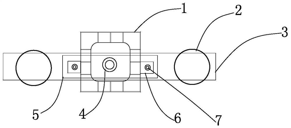
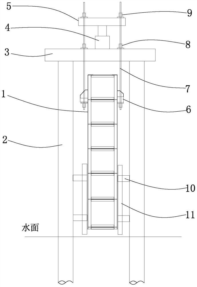
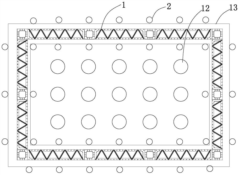
[0019] Such as figure 1 , figure 2 , image 3 As shown, the present invention provides a structure for lowering steel cofferdams by using steel pipe piles on drilling platforms. A load-bearing beam 3 is erected on the top of two opposite steel pipe piles 2 on both sides of the side plate, and a through-hole jack 4 is set on the load-bearing beam 3 facing the side plate of the steel cofferdam, and a pole beam 5 is set up on the jack. The positions of the load-bearing beams on the two side walls of the side slab of the weir are respectively welded with a lifting point 6, and the lifting point can adopt a corbel or ear plate structure, which is welded to the side wall of the steel cofferdam. The lower end of a suspension rod 7 passes through the suspension point 6 and is anchored at the bottom of the suspension point. The upper end of the suspension rod 7 passes through the load-bearing beam 3, the jack 4, and the pole beam 5 sequentially from bottom to top. A nut 8 is screwe...


PUM


Abstract

The invention provides a structure and method for lowering a steel cofferdam through drilling platform steel pipe piles. Each side plate of the steel cofferdam is located between two rows of drilling construction platform steel pipe piles; a bearing beam is erected on the tops of the two opposite steel pipe piles on the two sides of the side plate of the steel cofferdam, and a center hole jack is arranged at the position, right opposite to the side plate of the steel cofferdam, of the bearing beam; a shoulder pole beam is erected on the jack; lifting points are welded to the positions of the bearing beam on the two side walls of the steel cofferdam side plate respectively; the lower end of a lifting rod penetrates through the lifting points and is anchored to the bottoms of the lifting points; the upper end of the lifting rod sequentially penetrates through the bearing beam, the jack and the shoulder pole beam from bottom to top; the lifting rod is in threaded connection with a lower nut on the top face of the bearing beam; and an upper nut is screwed on the top surface of the shoulder pole beam. The existing structure is fully utilized, and on the premise that the construction cost is not increased, the problem that a large cantilever is stressed when a steel pile casing is used as a bearing structure to lower the steel cofferdam in the past is solved.

Description

technical field [0001] The invention belongs to the technical field of construction of bridge caps in water, and relates to a lowering structure and method of a steel cofferdam used for the construction of caps in water. Background technique [0002] During the construction of bridge submerged caps, steel casings are usually drilled at the pile foundation position first, and multiple rows of steel pipe piles are built around the steel casings, and the drilling construction platform is built with steel pipe piles; after the pile foundation drilling construction is completed, , Remove the drilling construction platform and steel pipe piles, lower the steel cofferdam on the periphery of the steel casing as a water retaining structure, and carry out capping construction in the steel cofferdam. Steel cofferdams are usually lowered as a whole by large floating cranes, or loosely assembled on site and then lowered section by section by jacks. The use of jacks to lower down section...

Claims


Application Information

Patent Timeline
Patent Type & Authority Applications(China)
IPC IPC(8): E02D15/08E02D19/04
CPCE02D15/08E02D19/04E02D2300/0029
Inventor 王安文吴曼薛飞王佳张曼于策
Owner ROAD & BRIDGE INT
Why Eureka
Try Eureka