
Range hood

A range hood and flue gas technology, applied in the direction of removing oil fume, household stove/stove, heating method, etc., can solve the problems of no major change in the flow path of oil fume, increasing the workload of cleaning oil cups, and a large number of oil cups, etc. To avoid the problem of running smoke, improve the overall effect of absorbing oil fume, and achieve the effect of uniform flow of oil fume

Active Publication Date: 2021-07-23
NINGBO FOTILE KITCHEN WARE CO LTD
View PDF7 Cites 1 Cited by
  • Summary
  • Abstract
  • Description
  • Claims
  • Application Information

AI Technical Summary

Problems solved by technology

[0005] However, this patent also has the following problems: First, the cross-sections of the first air duct body and the second air duct body are V-shaped, and the front ends protrude toward the center of the air duct. This oil guide structure makes each air duct Each body needs to be equipped with an oil cup correspondingly, resulting in a large number of oil cups and increasing the workload of subsequent cleaning of the oil cups
Secondly, the above-mentioned range hood with an oil-free mesh air duct structure is a European-style top-suction range hood. Although there is no oil net, it is still only the middle smoking mode, and its smoke inlet and oil fume flow path are not large. Changes, when a large amount of oil fume is generated, there is still the phenomenon of oil fume escape

Method used


Image

  • Range hood
  • Range hood
  • Range hood

Examples


Embodiment Construction

[0036] The present invention will be further described in detail below in conjunction with the accompanying drawings and embodiments.

[0037] In describing the present invention, it is to be understood that the terms "center", "longitudinal", "transverse", "length", "width", "thickness", "upper", "lower", "front", " Back", "Left", "Right", "Vertical", "Horizontal", "Top", "Bottom", "Inner", "Outer", "Clockwise", "Counterclockwise", "Axial", The orientation or positional relationship indicated by "radial", "circumferential", etc. is based on the orientation or positional relationship shown in the drawings, and is only for the convenience of describing the present invention and simplifying the description, rather than indicating or implying the referred device or element must have a particular orientation, be constructed, and operate in a particular orientation, and since the disclosed embodiments of the invention may be arranged in different orientations, these directional ter...


PUM


Abstract

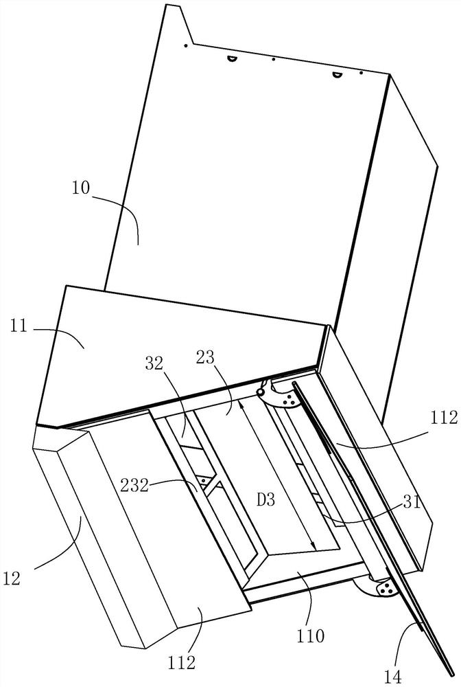
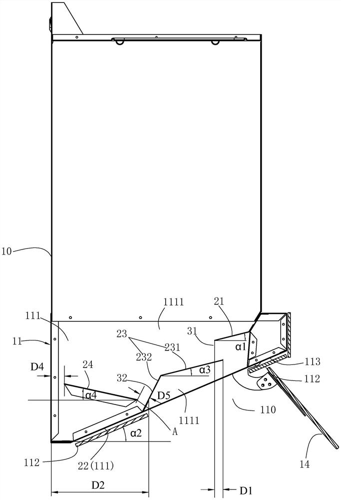
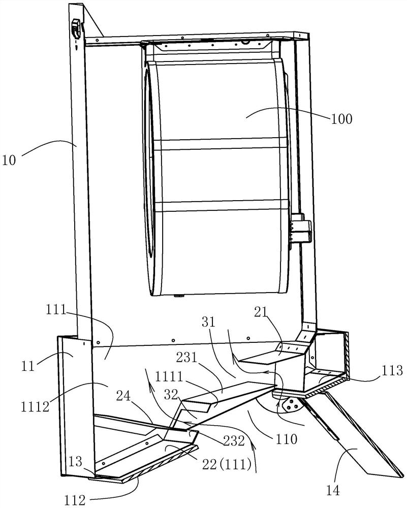
The invention relates to a range hood. The range hood comprises an exhaust fume collecting hood, a first oil guide plate, a second oil guide plate, an oil cup and a third oil guide plate; the exhaust fume collecting hood is provided with an exhaust fume collecting cavity and an air inlet, the first oil guide plate is arranged in the exhaust fume collecting cavity, is located at the front part of the exhaust fume collecting hood, and is obliquely arranged backwards from top to bottom, and the second oil guide plate is arranged in the exhaust fume collecting cavity, is located at the rear part of the exhaust fume collecting hood, and is obliquely arranged backwards from top to bottom; the oil cup is arranged, and the third oil guide plate is arranged in the exhaust fume collecting cavity, is obliquely arranged backwards from top to bottom, and is used for receiving oil dripping from the first oil guide plate and guiding the oil to the second oil guide plate; and the third oil guide plate, the first oil guide plate and the second oil guide plate jointly divide the exhaust fume collecting cavity into a first cavity corresponding to the upstream of the exhaust fume flowing direction and a second cavity corresponding to the downstream of the exhaust fume flowing direction, and the front side and the rear side of the third oil guide plate are provided with a first air suction opening and a second air suction opening. Through the cooperation of all the oil guide plates, the purpose of guiding the oil can be achieved, the exhaust fume flowing path can be changed, exhaust fume is rectified, and then the oil fume suction effect is improved.

Description

technical field [0001] The invention relates to the technical field of kitchen appliances, in particular to a range hood. Background technique [0002] Range hoods are becoming more and more popular in Chinese families and have become an indispensable household appliance in the kitchen. With the in-depth study of residents' cooking habits and kitchen environment, range hoods have made certain achievements in product types, technical content, standardization and other aspects. [0003] At present, most of the range hoods on the market adopt the structure of oil filter plate and refueling cup. One side or the conical bottom of the oil filter plate is equipped with a corresponding oil storage structure, that is, an oil cup. After the oil adheres to the oil filter plate, it flows into the oil cup and is stored in the oil cup. For example, the application number is CN201610543688.7 (announcement No. is CN106016404A) shown in " a kind of range hood with auxiliary air inlet chann...

Claims


Application Information

Patent Timeline
Patent Type & Authority Applications(China)
IPC IPC(8): F24C15/20
CPCF24C15/20
Inventor 刘元卉申志贤
Owner NINGBO FOTILE KITCHEN WARE CO LTD
Learn More