Range hood and control method thereof

A technology for range hoods and range hoods, which is applied in the direction of oil fume removal, heating methods, lighting and heating equipment, etc., and can solve the problems of smoke from the external test stove and poor smoking effect

Pending Publication Date: 2022-01-21
HANGZHOU ROBAM APPLIANCES CO LTD
View PDF0 Cites 0 Cited by
  • Summary
  • Abstract
  • Description
  • Claims
  • Application Information

AI Technical Summary

Problems solved by technology

[0003] The object of the present invention is to provide a range hood and a control method for the range hood, so as to alleviate the technical problems of the range hood in the prior art that the smoke from the external detection stove is running out and the smoking effect is poor.

Method used


Image

  • Range hood and control method thereof
  • Range hood and control method thereof
  • Range hood and control method thereof

Examples


Embodiment 1

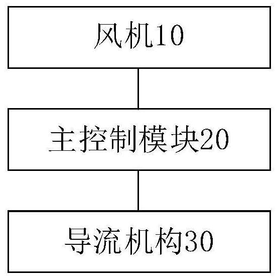
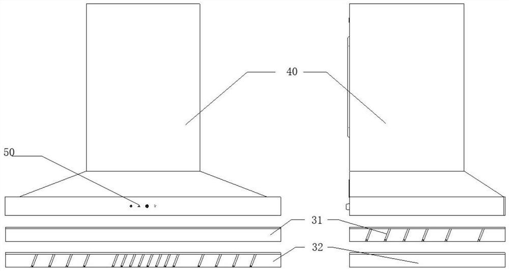
[0031] figure 1 A structural block diagram of a range hood provided by the present invention, such as figure 1 As shown, the range hood includes: a hood cavity 40 ( figure 1 Not shown in ) and fan 10 , the fan 10 is installed in the hood cavity 40 , the range hood also includes: a main control module 20 and a flow guiding mechanism 30 .

[0032] The main control module 20 is respectively connected with the fan 10 and the flow guiding mechanism 30 ; the flow guiding mechanism 30 is installed at the air inlet below the hood cavity 40 .

[0033] The main control module 20 is used for determining the wind force adjustment command and the direction adjustment command based on the target parameters of the stove, and sending the wind force adjustment command to the blower 10 , and sending the direction adjustment command to the flow guiding mechanism 30 .

[0034] The fan 10 is used to adjust the operating wind power according to the wind power adjustment command.

[0035] The air...

Embodiment 2

[0069] The embodiment of the present invention also provides a control method of the range hood, the control method of the range hood is applied to implement the range hood provided in the first embodiment above, the control method of the range hood provided in the embodiment of the present invention is as follows Make a specific introduction.

[0070] Figure 6 A flow chart of a control method for a range hood provided in an embodiment of the present invention, as shown in Figure 6 As shown, the control method specifically includes the following steps:

[0071] Step S102, monitoring the target parameters of each burner in the cooker.

[0072] Wherein, the target parameter includes at least one of the following: smoke concentration, operating power, and soot amount.

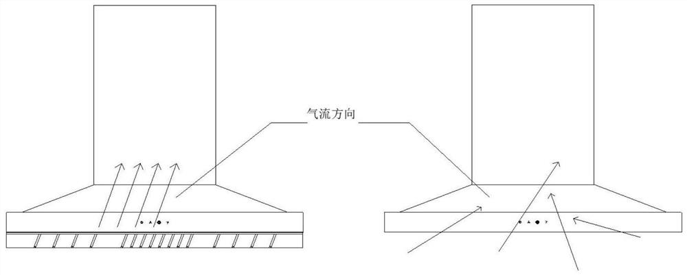
[0073] Step S104, based on the target parameters, it is judged whether the direction of the air inlet of the range hood is aligned with the stove with the greatest wind demand.

[0074] Wherein, the correspo...


PUM


Abstract

The invention provides a range hood and a control method of the range hood, and relates to the technical field of kitchen appliances. The range hood comprises a range hood cavity and a fan, the fan is mounted in the range hood cavity, and the range hood further comprises a main control module and a flow guide mechanism; the main control module is connected with the fan and the flow guide mechanism; the flow guide mechanism is mounted at an air inlet below the range hood cavity; the main control module is used for determining a wind power adjusting instruction and a direction adjusting instruction based on target parameters of cooking ranges, sending the wind power adjusting instruction to the fan and sending the direction adjusting instruction to the flow guide mechanism; the fan is used for adjusting operation wind power according to the wind power adjusting instruction; and the flow guide mechanism is used for adjusting the direction of the air inlet according to the direction adjusting instruction. According to the range hood, the flow guide mechanism is arranged, so that the aim of automatically adjusting the direction of the air inlet and the wind power according to the target parameters of each cooking range can be achieved, smoke leakage of the cooking ranges on the outer side is effectively prevented, and the overall smoke suction effect of the range hood is improved.

Description

technical field [0001] The invention relates to the technical field of kitchen appliances, in particular to a range hood and a control method for the range hood. Background technique [0002] With the development of science and technology, smart kitchen appliances have become the development trend of kitchen appliances in the future. Among them, hoods and stoves are the most basic parts of kitchen appliances. How to more conveniently control the linkage between hoods and stoves is the primary issue in the development of smart kitchen appliances. The existing smoke cooker linkage system can automatically adjust the wind power of the smoke machine by judging the gear position and firepower of the cooker, which can avoid cumbersome operations for users. However, when multiple stoves are used at the same time (such as three-eye stoves and four-eye stoves), the hood cannot accurately adjust the wind force taking into account the firing conditions of multiple stoves, especially t...

Claims


Application Information

Patent Timeline
Patent Type & Authority Applications(China)
IPC IPC(8): F24C15/20
CPCF24C15/20F24C15/2021
Inventor 任富佳李信合方宇佳郑桐福张富元周定锋朱世民白青松王文龙
Owner HANGZHOU ROBAM APPLIANCES CO LTD
Why Eureka
Try Eureka