Wide-angle optical lens
An optical lens, wide-angle technology, applied in the direction of optics, optical components, instruments, etc.
- Summary
- Abstract
- Description
- Claims
- Application Information
AI Technical Summary
Problems solved by technology
Method used
Image


Examples
Embodiment 1
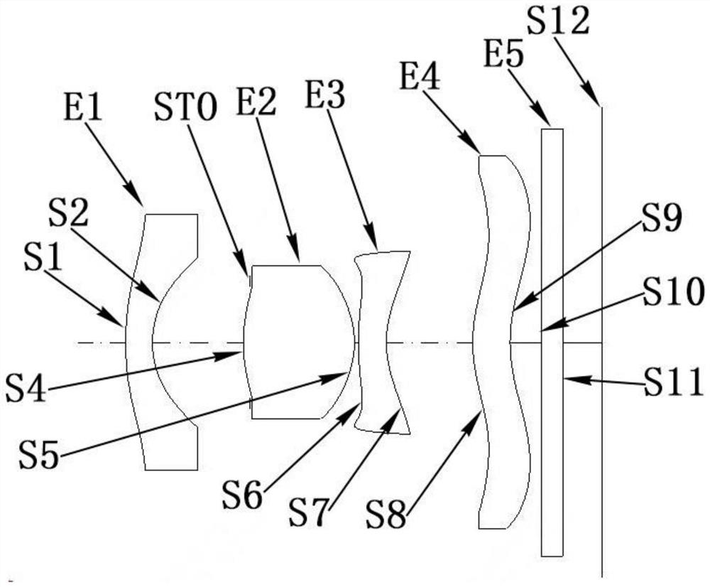
[0068] Refer to the following figure 1 , Figure 2A to Figure 2D An optical lens according to Embodiment 1 of the present invention will be described. figure 1 A schematic structural view of the optical lens according to Embodiment 1 of the present invention is shown.
[0069] Such as figure 1 As shown, the optical lens according to the exemplary embodiment of the present invention includes in sequence from the object side to the image side along the optical axis: a first lens E1, a stop STO, a second lens E2, a third lens E3, and a fourth lens E4, Filter E5 and imaging surface S12.
[0070] Wherein, the first lens E1 has negative refractive power, its object side S1 is convex, and the image side S2 is concave; the second lens E2 has positive refractive power, its object side S4 is convex, and the image side S5 is convex; the third lens E3 has a negative refractive power, its object side S6 is convex, and its image side S7 is concave; the fourth lens E4 has positive refrac...
Embodiment 2
[0093] Refer to the following image 3 , Figure 4A to Figure 4D An optical lens according to Embodiment 2 of the present invention will be described. In this embodiment and the following embodiments, for the sake of brevity, descriptions similar to those in Embodiment 1 will be omitted. image 3 A schematic structural diagram of an optical lens according to Embodiment 2 of the present invention is shown.
[0094] Such as image 3 As shown, the optical lens according to the exemplary embodiment of the present invention includes in sequence from the object side to the image side along the optical axis: a first lens E1, a stop STO, a second lens E2, a third lens E3, and a fourth lens E4, Filter E5 and imaging surface S12.
[0095] Wherein, the first lens E1 has negative refractive power, its object side S1 is convex, and the image side S2 is concave; the second lens E2 has positive refractive power, its object side S4 is convex, and the image side S5 is convex; the third len...
Embodiment 3
[0115] Refer to the following Figure 5 , Figure 6A to Figure 6D An optical lens according to Embodiment 3 of the present invention will be described. Figure 5 A schematic structural diagram of an optical lens according to Embodiment 3 of the present invention is shown.
[0116] Such as Figure 5 As shown, the optical lens according to the exemplary embodiment of the present invention includes in sequence from the object side to the image side along the optical axis: a first lens E1, a stop STO, a second lens E2, a third lens E3, and a fourth lens E4, Filter E5 and imaging surface S12.
[0117] The first lens E1 has negative refractive power, its object side S1 is convex, and its image side S2 is concave; the second lens E2 has positive refractive power, its object side S4 is convex, and its image side S5 is convex; the third lens E3 has Negative refractive power, the object side S6 is convex, and the image side S7 is concave; the fourth lens E4 has positive refractive p...
PUM
 Abstract
Description
Claims
Application Information