Sound insulation structure with air interlayer and ventilation while sound insulation

一种空气夹层、隔声的技术,应用在隔音、隔绝层、建筑构件等方向,能够解决整体结构复杂、有能耗等问题,达到提高隔声性能、增加散射、隔声性能提高的效果

Active Publication Date: 2022-07-15
XI AN JIAOTONG UNIV
View PDF6 Cites 0 Cited by
  • Summary
  • Abstract
  • Description
  • Claims
  • Application Information

AI Technical Summary

Problems solved by technology

The invention patent with the application number 201611093387.5 proposes a staggered sound insulation structure in which passive sound insulation units and active sound insulation units are mixed. It already has the functions of ventilation and heat dissipation, but it still has active units. The addition of active units makes The overall structure is relatively complex and consumes energy when used, so it is not suitable for underdeveloped areas

Method used


Image

  • Sound insulation structure with air interlayer and ventilation while sound insulation
  • Sound insulation structure with air interlayer and ventilation while sound insulation
  • Sound insulation structure with air interlayer and ventilation while sound insulation

Examples


Embodiment 1

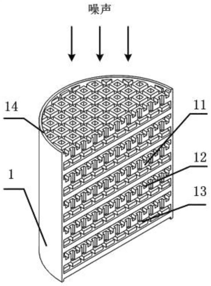
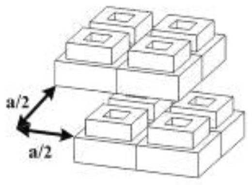
[0023] As shown in Figure 1(a), in this embodiment, the overall shape of the sound insulation structure of the staggered arrangement of grooved perforated plates, that is, the shell 1 is cylindrical, the diameter of the shell 1 is 29.8mm, and the thickness is 30mm. Its overall shape and thickness can be made according to actual engineering needs. This embodiment includes a casing 1 and several layers of perforated plates 11 arranged in the casing 1 , and two adjacent perforated plates 11 are arranged in a staggered manner and are provided with air interlayers 13 . A plurality of grooves 12 are arranged on one side of the perforated plate in two mutually perpendicular perforation directions. Among them, the thickness of the perforated plate is 2mm; the perforated section is square, and the side length of the square is 1mm; the perforation spacing of the perforated plate is 3mm; the width of the groove is 0.8mm, the depth is 0.8mm; the thickness of the air interlayer is 1mm. Th...

Embodiment 2

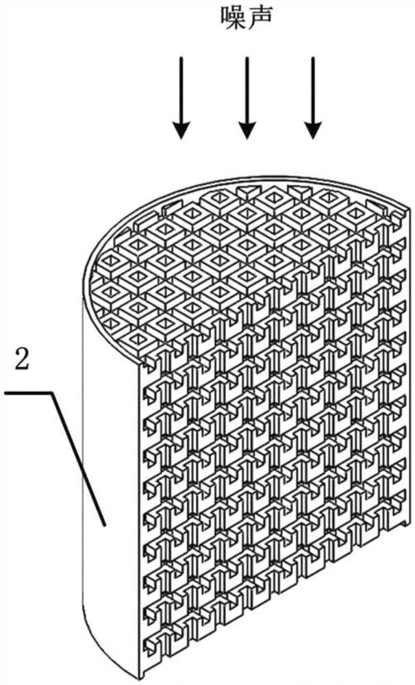
[0028] In this embodiment, the overall shape of the sound insulation structure of the staggered arrangement of the grooved perforated plates is cylindrical, the diameter of the sample is 29.8 mm, and the thickness is 60 mm. In this embodiment, the sound insulation structure of slot-type perforated plates arranged in a row is selected as a comparison, and the overall shape is cylindrical and the thickness is 60mm.

[0029] The SW477 impedance tube manufactured by Beijing Shengwang Shengdian Technology Co., Ltd. was used to test the transmission loss of the staggered sound insulation structure of the grooved perforated plates involved in Example 2 and the sound insulation knots arranged in a row. The test frequency range is 1000Hz-6300Hz. During the test, the side of the sample with the grooves faces the noise source.

[0030] Figure 5 For the same shape (the sample diameter is 29.8mm and the thickness is 60mm), the change of the transmission loss of the staggered sound insul...


PUM


Abstract

The invention discloses a sound insulation structure containing an air interlayer and ventilating and ventilating while sound insulation, which is characterized in that: the sound insulation structure comprises: a shell (1), and a plurality of A perforated plate (11) provided with a groove (12) on one side of the layer, and the side of the perforated plate (11) provided with the groove faces the noise source; a perforated position is located between two adjacent perforated plates (11). The staggered arrangement is provided with an air interlayer (13), wherein the staggered arrangement is that the two adjacent perforated plates (11) are staggered according to the relative positions of the perforations in two mutually perpendicular perforation directions, and the staggered distance is the distance between the perforations. half; the perforation method of the perforated plate (11) is equal-spaced perforation, and the perforated cross-section of the perforated plate is square or circular; the groove (12) on one side of the perforated plate (11) is two perpendicular The perforation directions are arranged; the spacing of the grooves (12) is the perforation spacing of the perforated plate.

Description

technical field [0001] The invention relates to the technical field of sound insulation, in particular to a sound insulation structure that contains an air interlayer and is ventilated and breathable while sound insulation. Background technique [0002] Traffic noise, social life noise, factory noise, construction noise, etc. are common noise sources, which threaten the physical and mental health of residents. With the improvement of living standards, people pay more and more attention to environmental quality, and noise has become a hot issue in the process of environmental governance. Sound insulation wall, sound insulation screen, sound insulation cover, etc. are often used to control the transmission of airborne sound, so that the noise is blocked in the transmission path, thereby reducing the noise. Holes, etc. will affect the sound insulation effect of sound insulation walls, etc., so sound insulation components such as sound insulation walls are generally not allowed...

Claims


Application Information

Patent Timeline
Patent Type & Authority Patents(China)
IPC IPC(8): E01F8/00E04B1/82
CPCE01F8/00E04B1/82
Inventor 屈治国张秀海
Owner XI AN JIAOTONG UNIV
Why Eureka
Try Eureka