[0012] The pet door disclosed in U.S. Pat. No. 5,177,900 suffers from the problem that the apparatus is quite complicated to manufacture both mechanically and electrically. Electrical components provided for driving the motor and operating the
detector are required to be disposed at different locations in the pet door, thereby increasing manufacturing cost and complexity. Moreover, for a dog door requiring latching so as to prevent both unauthorised ingress and ingress with respect to the building, this requires two of the detectors to be provided, one on each side of the pet door. Again, this increases manufacturing cost and complexity. Furthermore, since the detector is required to define a
receiver region extending a selected angular width above the horizontal in order for the detector to be able reliably to receive the required transmission
signal from the
transmitter of the pet collar, this means that the selector is liable to be covered by
dirt, scratched, or even damaged as a result of frequent animal passages through the pet door.
[0043] The present invention is at least partially predicated on the surprising discovery by the applicant that the
transmitter of
infrared radiation when mounted on a collar around the neck of a pet such as a cat or a dog, therefore to lie against the
throat of the animal in the normal way, does not need to operate in a “direct
line of sight” mode. Irrespective of the precise orientation of the infrared transmitter around the animal's neck, infrared radiation tends to be reflected off the fur or coat of the animal in a diffuse manner, and the degree of reflection is sufficiently high so as generally to cause infrared radiation to be directed forwardly of the animal. This reflection can in turn be reflected off the ground and then upwardly towards the
receiver which has a downwardly directed receiving zone. Sufficient infrared radiation is transmitted or reflected forwardly from the animal towards the pet door substantially independently of the orientation of the animal's head. Therefore the applicant has discovered that as a result of this phenomenon the infrared transmitter and
receiver do not need to operate in a direct
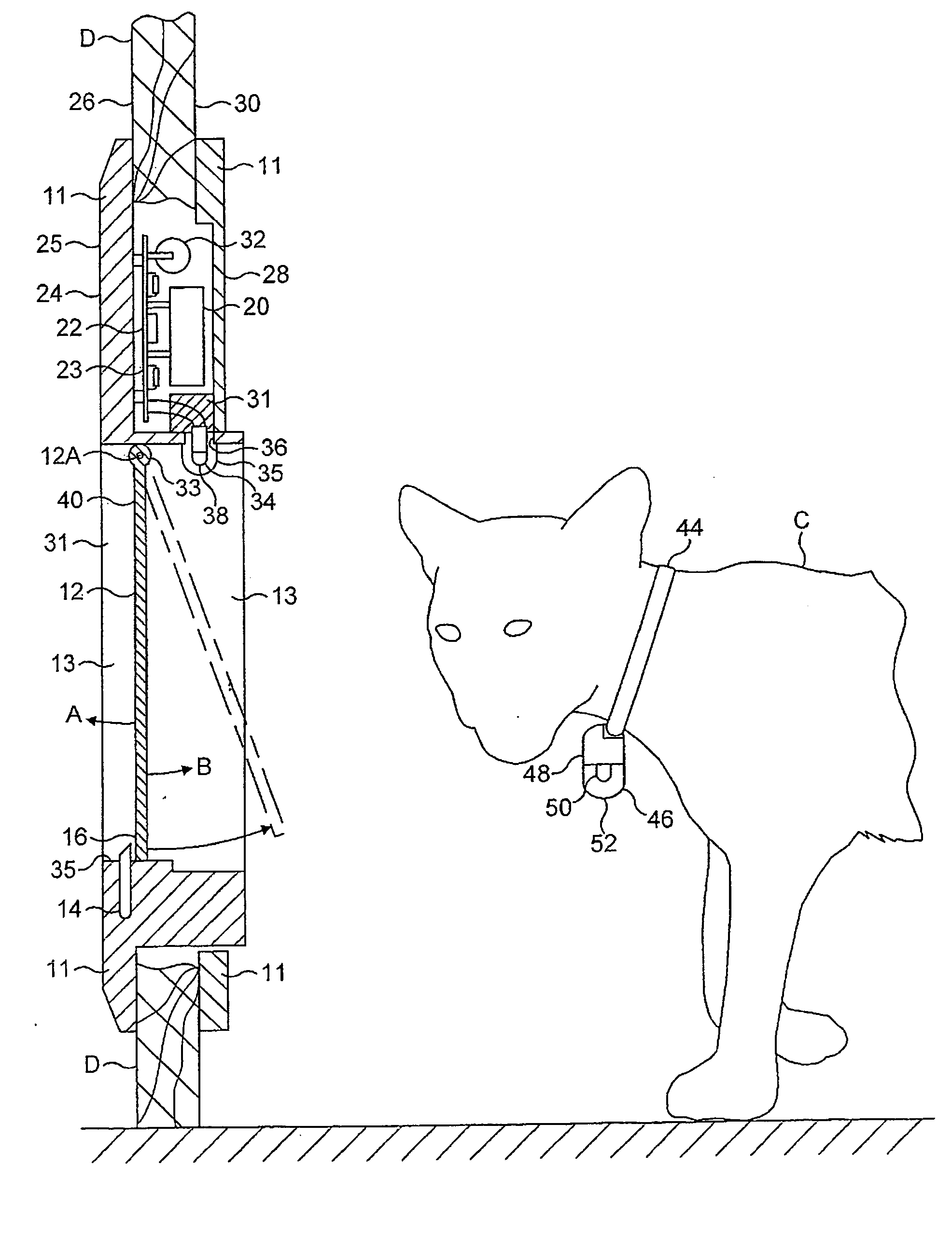
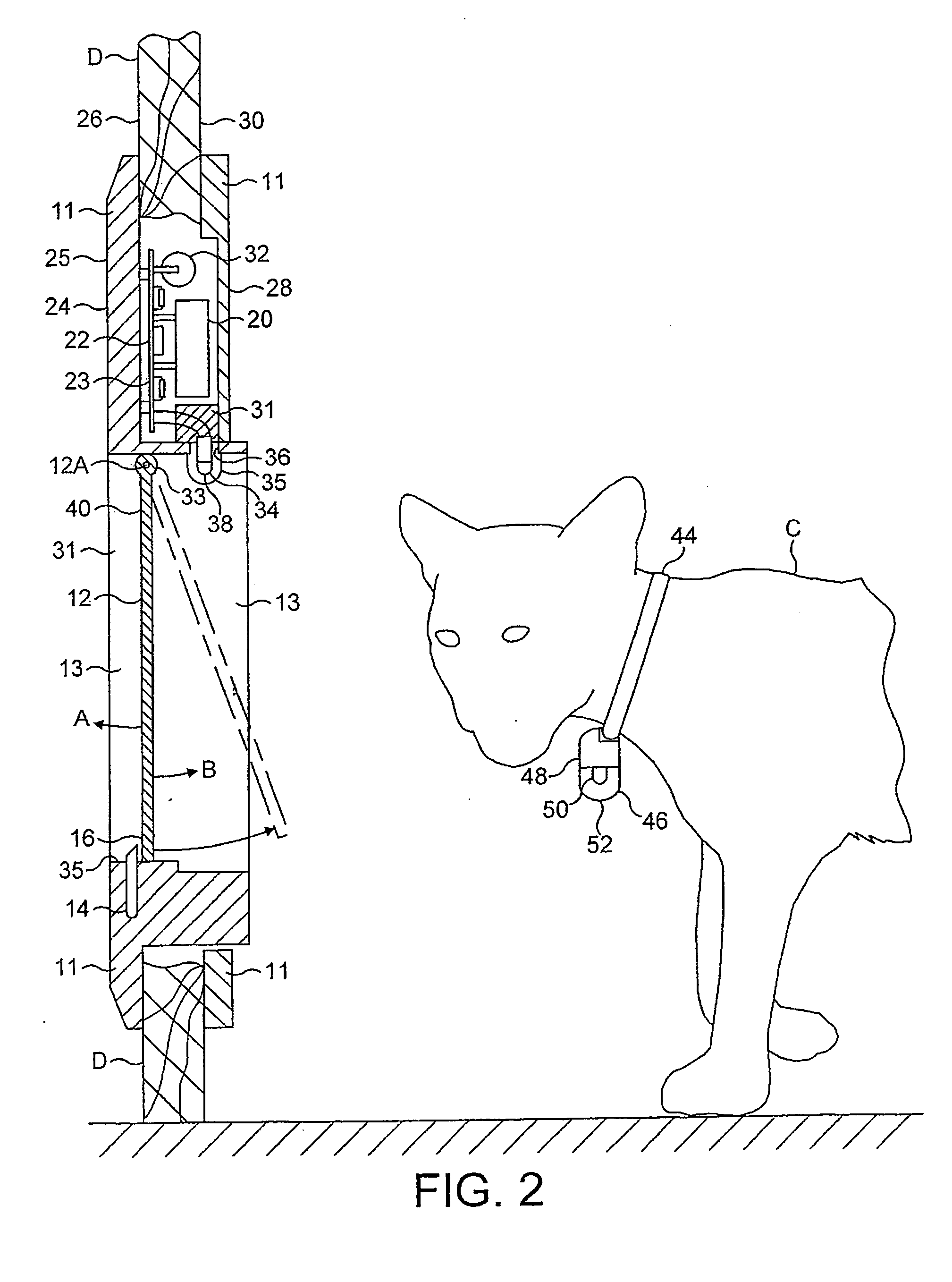
line of sight mode but may rather operate in a reflective mode, using the animal itself to cause some reflection of the radiation, with some radiation additionally been reflected off the ground toward the detector. By operating in a reflective mode the infrared radiation detector can be located above a lower edge of the pet door, particularly above the door flap, more particularly above the axis of a hinged pet door having a horizontally oriented hinge along an upper edge of a door flap. This provides three advantages.
[0044] A first
advantage is that with such a location of the
infrared detector, the
infrared detector can be provided integral with the circuitry for operating the latching mechanism of the pet door. The latching mechanism is typically located in an upper portion of the pet door to enable the lower portion to be provided with the door flap and the associated opening. The infrared radiation detector can even be mounted directly on a circuit board for the control circuitry. This reduces the complexity of the cat flap, thereby reducing manufacturing costs both with regard to component costs, and manufacturing complexities and
assembly time.
[0045] A second
advantage is that since the infrared radiation detector is always located above the pathway of the animal through the pet door, there is a significantly reduced chance of the detector becoming inadvertently covered with soil or
dirt or scratched or otherwise damaged as a result of passage of the animal through the pet door.
[0046] A further
advantage is that for a dog door, where, as described hereinabove, it is necessary to detect approach of a dog from each of two sides of the dog door so that it is latched against inadvertent opening in both directions, by the provision of an infrared radiation detector above the door flap, this can enable a single detector to be provided which has a detection zone encompassing both sides of the pet door and so is responsive to infrared radiation from either side of the pet door. Also, the single detector can operate a common latch, preventing the door from opening in both directions, by means of a single drive
system. This is in contrast to some known dog doors which use two detectors and two latch mechanisms, and drive systems therefor, one for each direction of latching, although these other arrangements are utilisable in accordance with the invention. This enables a significant cost saving as compared to know dog doors having two separate detector systems, each on a respective side of the door, for example as disclosed in U.S. Pat. No. 5,813,364. When the pet door is battery operated, this also increases the battery life.
[0047] The present invention is also predicated at least partly on the discovery that for reliable operation of the infrared pet door, in particular controlling an accurate detection range for the device for different size animals and under varying ambient light conditions, while minimising battery
power consumption, particularly in the collar key worn by the pet which incorporates an infrared transmitter, beam angles of the infrared transmitter and receiver should ideally be preselected, and also the angle of the beam emitted from the transmitter worn by the pet should ideally be preselected.

