Continuous nerve block assembly

Inactive Publication Date: 2008-03-06
COOK MEDICAL TECH LLC +1
View PDF17 Cites 84 Cited by
  • Summary
  • Abstract
  • Description
  • Claims
  • Application Information

AI Technical Summary

Benefits of technology

[0017] The present invention addresses the limitations of the prior art. An assembly is provided for continuous blockage of a nerve of a patient. The assembly includes a needle comprising a hollow needle conduit having a shaft portion and a tip portion, a generally non-conductive layer disposed along a length of the conduit shaft portion, and an echogenic surface extending along at least a portion of the needle. A catheter is sized to be received in the shaft portion of the ne

Problems solved by technology

When this process is done with a needle, the risk of damaging a nerve fiber is high, with the possible result of permanent nerve injury.
This technique has been largely abandoned due to the high possibility of such permanent injury.
A limitation of this technique is that it is a blind technique that is carried out based on a general understanding of the surface anatomy of the particular nerve to be blocked, and without a precise location of the nerve under the skin.
One major shortcoming of the 2D ultrasound technique is that the needle is often not easily visible in the plane of the 2D ultrasound beam.
As a result, it is often ergono

Method used


Image

  • Continuous nerve block assembly
  • Continuous nerve block assembly
  • Continuous nerve block assembly

Examples


Example

DETAILED DESCRIPTION OF THE DRAWINGS AND THE PRESENTLY PREFERRED EMBODIMENTS

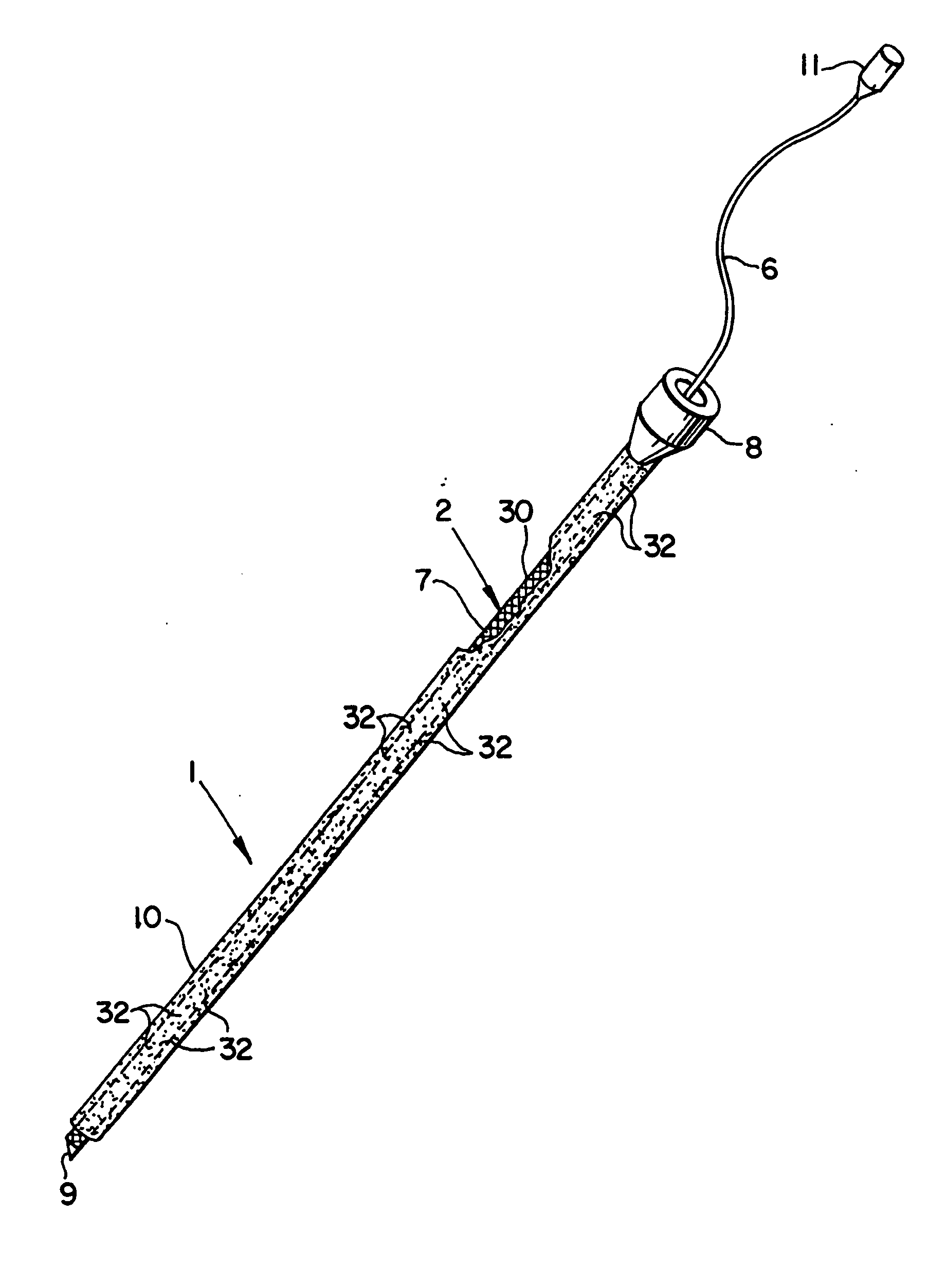
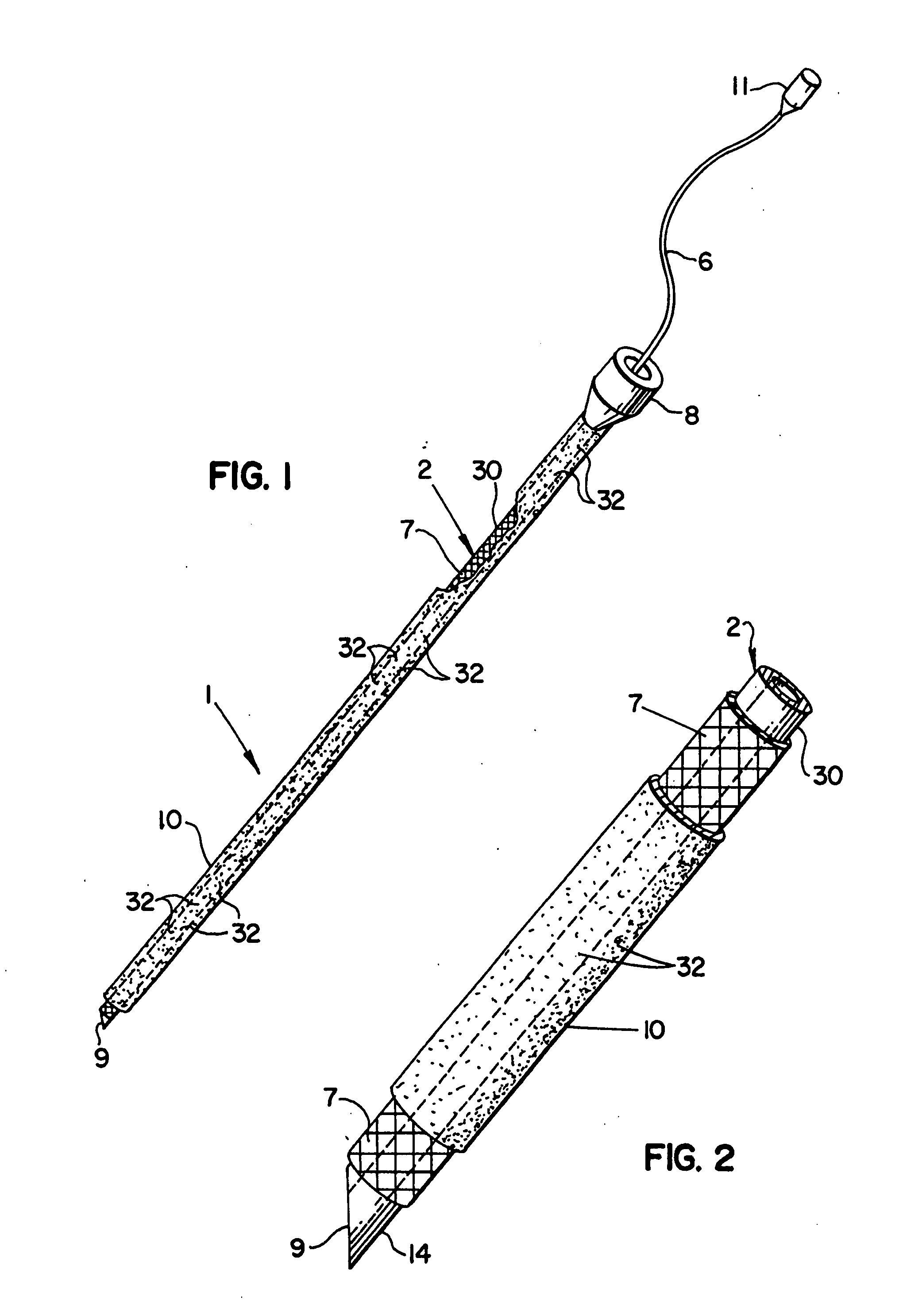
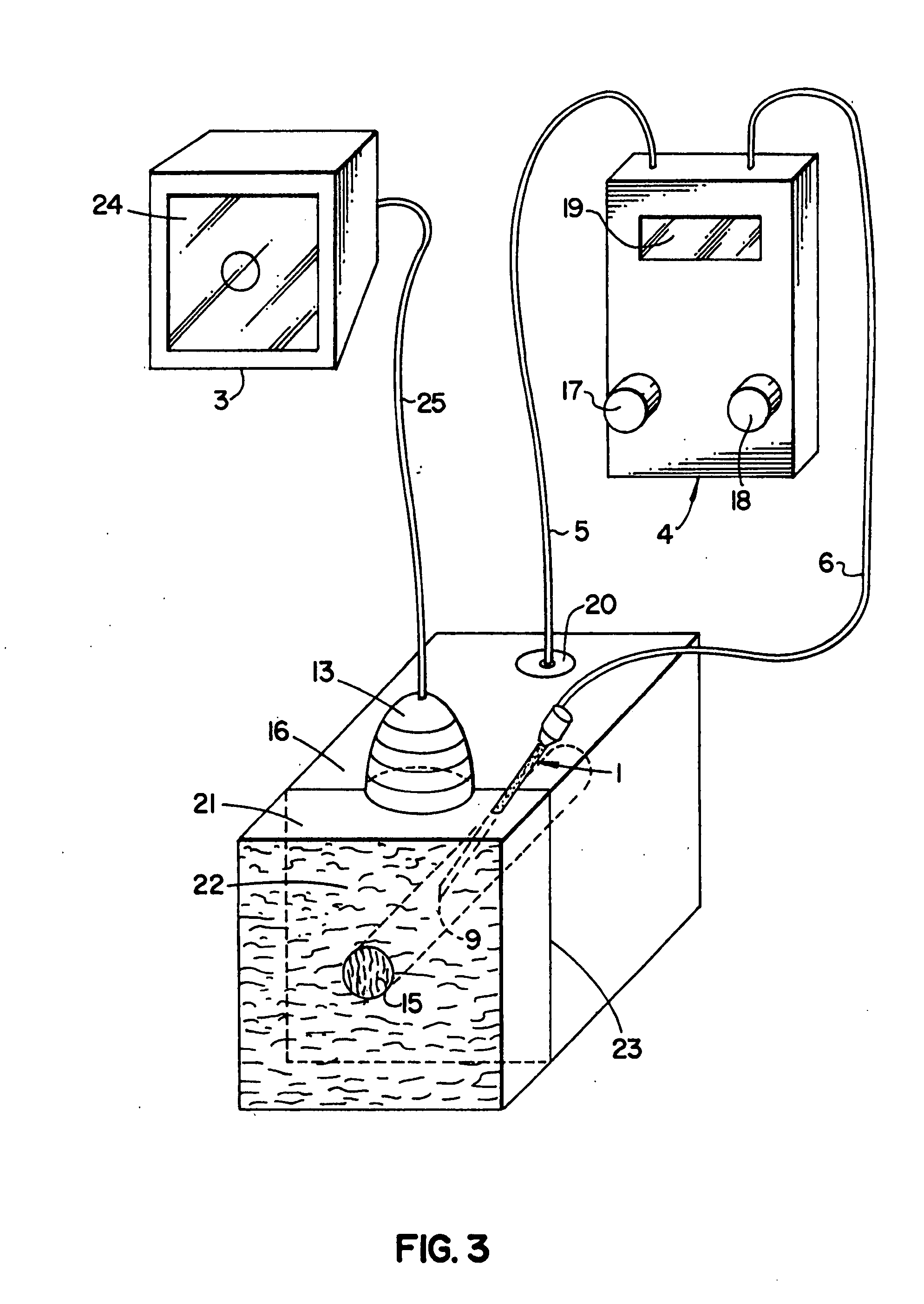
[0029] For the purposes of promoting an understanding of the principles of the invention, reference will now be made to the embodiments illustrated in the drawings, and specific language will be used to describe the same. It should nevertheless be understood that no limitation of the scope of the invention is thereby intended, such alterations and further modifications in the illustrated device, and such further applications of the principles of the invention as illustrated therein being contemplated as would normally occur to one skilled in the art to which the invention relates.

[0030] In the following discussion, the terms “proximal” and “distal” will be used to describe the opposing axial ends of the needle portion of the inventive assembly, as well as the axial ends of various components of the assembly. The term “proximal” is used in its conventional sense to refer to the end of the needle (or compone...


PUM


Abstract

An assembly and method for continuous blockage of a nerve in a patient. The assembly includes a needle comprising a hollow needle conduit having a shaft portion and a tip portion, a generally non-conductive layer disposed along a length of the conduit shaft portion, and an echogenic surface extending along at least a portion of the needle. A catheter having a bore for transmittal of an anesthetic to the nerve is receivable in the shaft portion of said needle. Following insertion of the needle tip in the vicinity of the nerve by electrical nerve stimulation and ultrasound visualization, the catheter is passed through the needle conduit such that the distal end of the catheter extends beyond the distal tip of the needle. The catheter has an echogenic portion, such as a ribbon wrapped around the distal end of the catheter, and the catheter echogenic portion is guidable in the vicinity of the nerve under ultrasound imaging. Following placement of the catheter, the needle may be removed, leaving the catheter in position for delivering continuous, spaced doses of the anesthetic over a selected period of time.

Description

RELATED APPLICATION [0001] The present patent document is a continuation-in-part of application Ser. No. 11 / 635,931, filed Dec. 8, 2006, which claims the benefit of the filing date under 35 U.S.C. §119(e) of Provisional U.S. Patent Application Ser. No. 60 / 749,664, filed Dec. 12, 2005. Each of the foregoing applications is hereby incorporated by reference.BACKGROUND [0002] 1. Technical Field [0003] The present invention relates generally to an assembly for use in blocking a peripheral nerve of a patient to produce regional anesthesia. More particularly, the invention relates to an echogenic continuous nerve block assembly suitable for such use. The invention further relates to a method for continuously blocking a nerve. [0004] 2. Background Information [0005] It is a well known medical practice to produce regional anesthesia in a patient by depositing a local anesthetic along the path of one or more peripheral nerves. The success of the technique is largely dependent upon the ability...

Claims


Application Information

Patent Timeline
IPC IPC(8): A61M5/00
CPCA61B8/0833A61B8/0841A61N1/08A61B2017/3413A61B2019/5425A61B17/3401A61B2090/3925
Inventor ARNDT, GEORGE A.BOSEL, CHRISTOPHER D.
Owner COOK MEDICAL TECH LLC
Why Eureka
Try Eureka