Image display device

Inactive Publication Date: 2006-08-15
PANASONIC LIQUID CRYSTAL DISPLAY CO LTD +1
View PDF5 Cites 2 Cited by
  • Summary
  • Abstract
  • Description
  • Claims
  • Application Information

AI Technical Summary

Benefits of technology

[0006]Accordingly, it is a first object of the present invention to provide an image display device which can produce a multiple gray scale display, which image display device performs display by making use of the rotation of balls.
[0007]It is a second object of the present invention to provide an image display device which produces a display by making use of the rotation of balls and which can realize a multi-color display of not less than 64 colors.
[0008]It is a third object of the present invention to provide an image display device which produces a display by making use of the rotation of balls and which can resolve sticking which may occur when the display is performed for a long period of time.
[0009]It is a fourth object of the present invention to provide an image display device which produces a display by making use of the rotation of balls and which can enhance reflectance, thus providing a bright image display device.

Problems solved by technology

However, there still remains a drawback in that it is difficult to produce a multiple gray scale display using this method.
Accordingly, there still remains a problem in that it is difficult to realize a multicolor display of not less than 64 colors, which exceeds the combination of primary colors and requires a gray scale display of each color.

Method used


Image

  • Image display device
  • Image display device
  • Image display device

Examples


embodiment 1

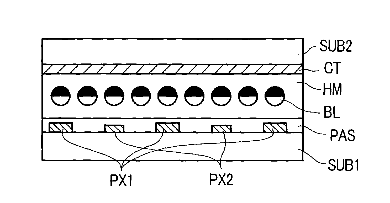
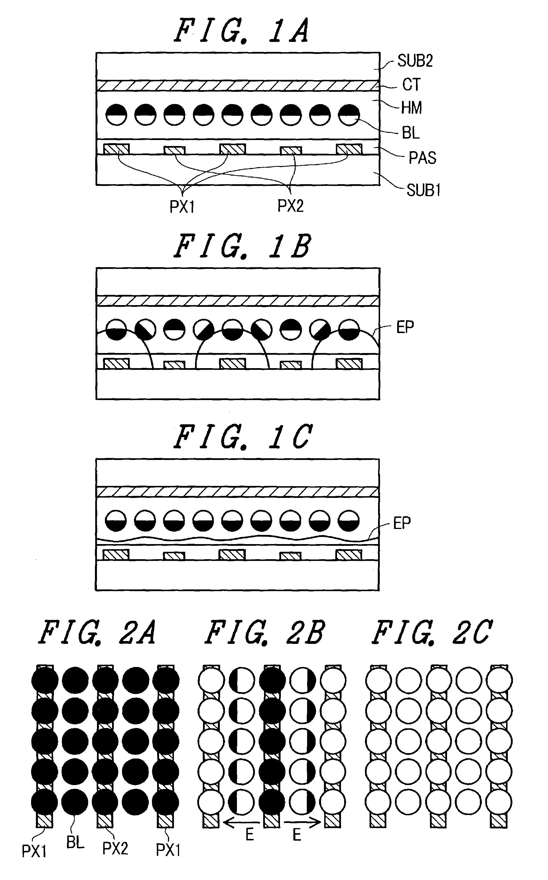
[0072]FIGS. 1A to 1C are schematic cross-sectional views of the structure of a pixel according to one embodiment of the present invention. Two types of electrodes PX1 and PX2 are formed on a first substrate SUB1, on which the electrodes PX1 and PX2 are arranged alternately. A protective film PAS is formed over the electrodes PX1, PX2 so as to protect these electrodes. A reference electrode CT is formed on the inner surface of a second substrate SUB2. Spherical bodies (electronic balls) BL are formed between the substrates SUB1, SUB2. Each electronic ball has two regions which differ in luminance, for example, wherein one region is formed as a black region and another region is formed as a white region. These electronic balls BL are supported by a support body HM. To facilitate the manufacture thereof, the electronic balls and the support body may be formed on the second substrate SUB2. In this case, the first substrate SUB1, which has a relatively complicated electrode arrangement, ...

embodiment 2

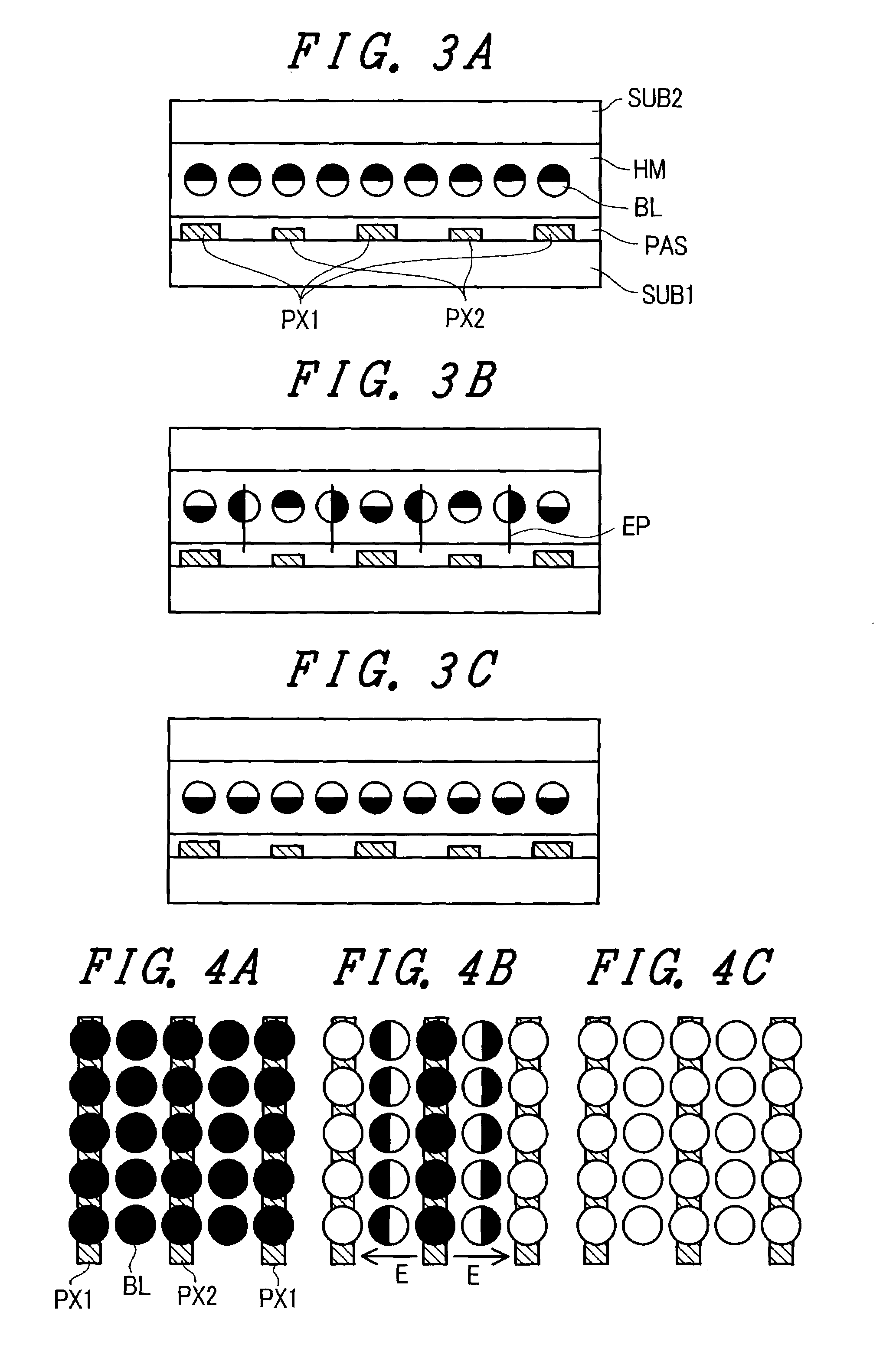
[0084]FIGS. 3A to 3C and FIGS. 4A to 4C are views which correspond to the views provided in FIGS. 1A to 1C and FIGS. 2A to 2C of the embodiment 1. The feature which makes the embodiment 2 different from the embodiment 1 lies in the fact that the reference electrode CT is not formed on the second substrate SUB2 side.

[0085]The reference electrode CT in the embodiment 1 contributes to the stabilization of the potential formed between the electrode PX1 and the electrode PX2. However, even when the reference electrode CT is eliminated, it is possible to realize substantially the same display. In this case, the manufacturing cost of the image display device can be reduced by an amount corresponding to the cost saving relating to the elimination of the reference electrode CT at the second substrate SUB2 side.

[0086]FIG. 3A shows a state in which the black portions of the electronic balls are charged positively, and +20 V, for example, is applied to the electrodes PX1 and the electrodes PX2....

embodiment 3

[0091]In the image display device using electronic balls, both the embodiment 1 and the embodiment 2 exhibit a novel and remarkable effect in that an enlargement of the viewing angle can be realized. This effect will be explained in conjunction with FIGS. 6A to 6H.

[0092]FIGS. 6B, 6C and 6D respectively show how the electronic ball is viewed in the respective directions b, c, d when the electronic ball assumes the state shown in FIG. 6A. In FIG. 6B, in which the electronic ball is viewed from directly above, the electronic ball exhibits a white appearance; while, in FIG. 6C, in which the electronic ball is viewed from the left direction, and in FIG. 6D, in which the electronic ball is viewed from the right direction, a major portion of the electronic ball exhibits a white appearance, although black is slightly mixed in the view. Accordingly, in a black-or-white binary display, there is only a small angle dependency with respect to the difference in luminance or difference in color, s...


PUM


Abstract

A multi-valued display is produced by an image display device using electronic balls. The image display device includes a first substrate and a second substrate and spherical bodies, which are sandwiched between the first substrate and the second substrate and which are rotatable. Each rotatable spherical body has at least two regions formed by dividing the spherical body in color, and at least first electrodes and second electrodes which apply an electric field to the rotatable spherical bodies. At least an electric field which is generated between the first electrode and the second electrode is applied to the rotatable spherical body, and the image display device further defines a plurality of regions which differ in the intensity of the electric field in the pixel.

Description

BACKGROUND OF THE INVENTION[0001]The present invention relates to an image display device; and, more particularly, the invention relates to an image display device which produces a display by making use of the rotation of electronic balls.[0002]In providing a thin image display device, there has been extensive development of liquid crystal display devices. However, with respect to liquid crystal display devices, there still remains the drawback that it is difficult to hold the same image for a long period of time. Recently, as a novel image display device which can solve this drawback, a system has been proposed in which a display is generated using rotatable electronic balls.[0003]To briefly explain this method, two hemispheres of the same ball are respectively coated in black and white to form a black region and a white region, and static electricity having either a plus polarity or a negative polarity is preliminarily imparted to the black region, for example. Then, this ball is ...

Claims


Application Information

Patent Timeline
IPC IPC(8): C09K19/52G02F1/17G02B26/02G06F3/041G09G3/20G09G3/34
CPCG02B26/026
Inventor YANAGAWA, KAZUHIKO
Owner PANASONIC LIQUID CRYSTAL DISPLAY CO LTD
Why Eureka
Try Eureka