Low-e glass annealing apparatus

Inactive Publication Date: 2021-11-18
COWIN DST CO LTD
View PDF0 Cites 0 Cited by
  • Summary
  • Abstract
  • Description
  • Claims
  • Application Information

AI Technical Summary

Benefits of technology

The present invention provides a low-E glass annealing apparatus that can solve thermal shock and energy efficiency problems of existing laser annealing methods while using a laser beam for annealing. The apparatus can form a low-E coating film while proceeding a glass plate. The reflective mirrors have cooling means on surfaces opposite to enhance reflectance, and a coating film is formed on the surfaces.

Problems solved by technology

Development of techniques which can achieve high energy efficiency by reducing energy loss in the main energy consuming sectors, such as an industrial site, a building and the like, is always an important issue.
However, it is disadvantageous in that the color is simple and the coating film is cloudy since use of various metals is limited.
However, compared with the hard low-E, coating hardness and durability are weak, and an edge stripping process facility is separately needed when a multilayer glass is manufactured.
A laser beam is generally obtained by expensive equipment, and although it is frequently used in the past to heat a bulky amount, it is known to be used much recently in an annealing process of a semiconductor substrate or a liquid crystal substrate.
However, since a conventional method of radiating a laser beam on the surface of a glass substrate concentrates high energy in a short time, it may invite abrupt change in temperature of the glass, and the glass plate itself may be damaged by thermal shock, and since a large proportion of the laser beam passes through or reflected by the glass plate, only about 10% of the entire laser output is used for heating to form a coating film, and thus the thermal efficiency is low.

Method used


Image

  • Low-e glass annealing apparatus
  • Low-e glass annealing apparatus
  • Low-e glass annealing apparatus

Examples


Embodiment Construction

[0037]Hereinafter, the present invention will be described in detail through the specific embodiments with reference to the accompanying drawings.

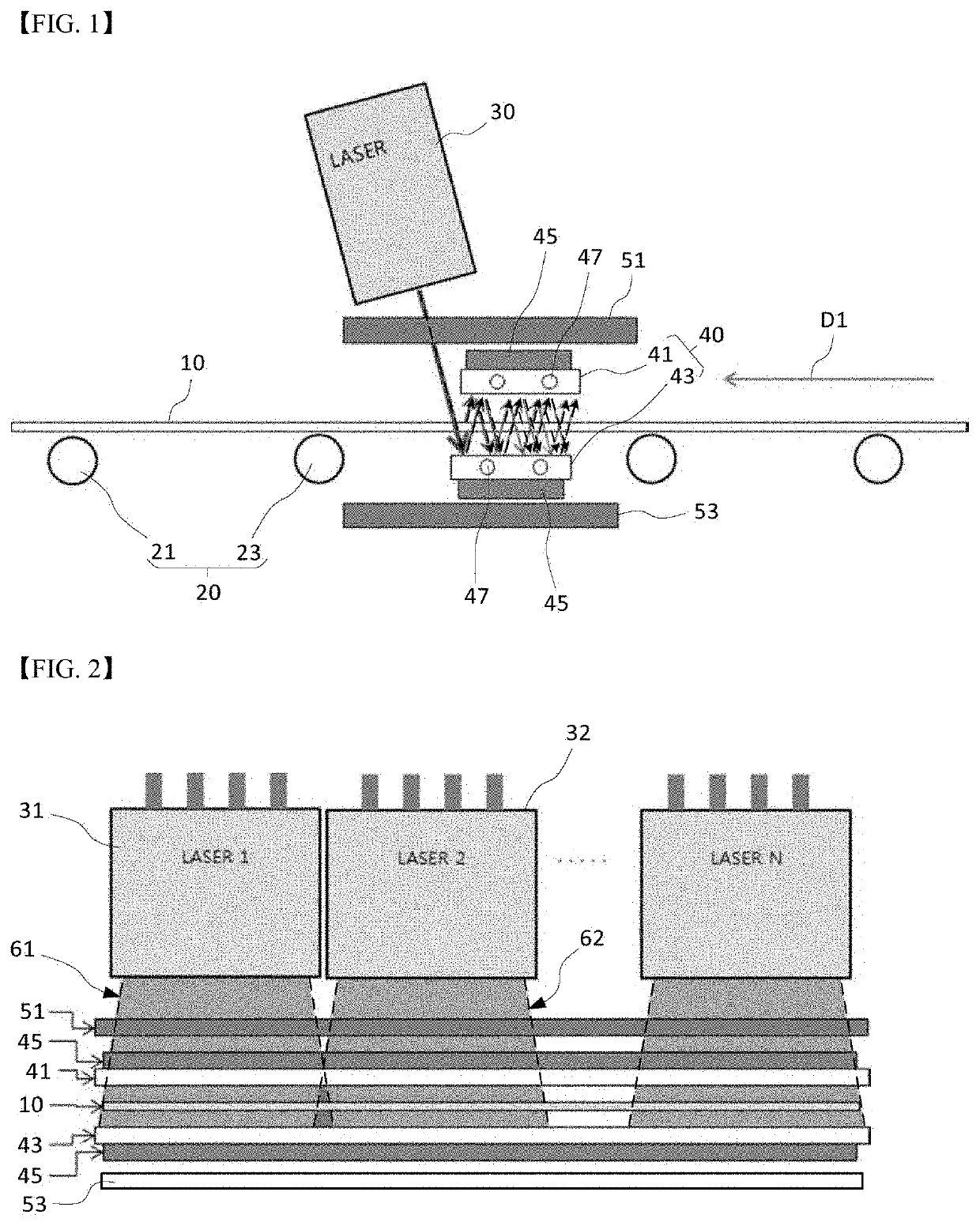
[0038]FIG. 1 conceptually shows the configuration of a low-E glass annealing system which anneals a glass substrate by heating, using a laser, a coating film already formed on the surface of a glass in the previous step while horizontally transferring the glass substrate to manufacture a low-E glass.

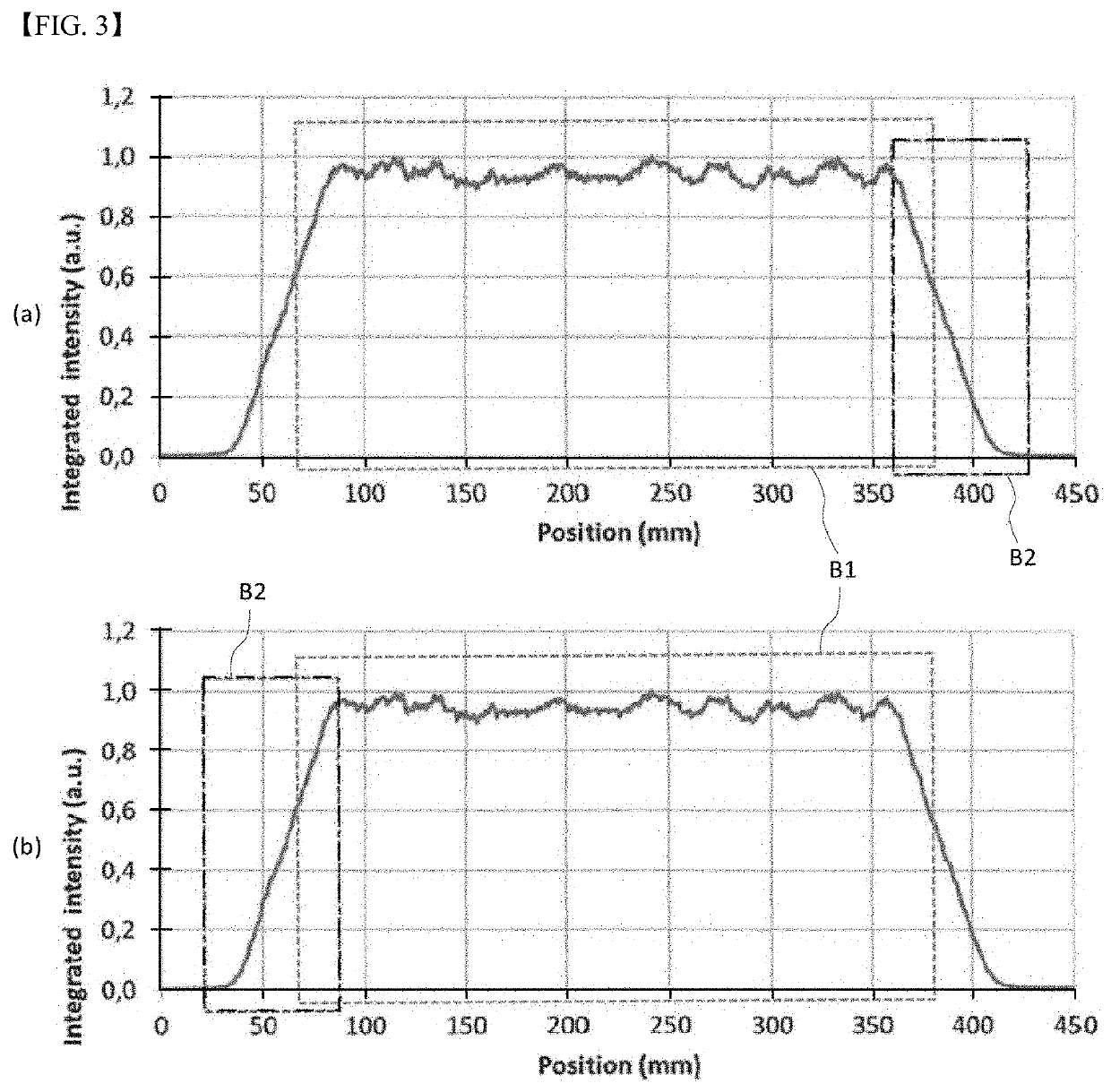
[0039]The low-E glass annealing system according to this embodiment basically includes a transfer device 20, a laser module 30 and a reflective mirror pair 40. The low-E glass annealing system irradiates a metal film on a glass substrate 10 with a laser beam so that annealing may take place while light energy of the laser beam is converted to thermal energy on the surface, to effectively crystallize the metal film and to have a low emissivity characteristic of the low-E glass including a metal coating film.

[0040]Here, a low-E coating film layer...


PUM

PropertyMeasurementUnit
Fractionaaaaaaaaaa
Angleaaaaaaaaaa
Light intensityaaaaaaaaaa

Abstract

Disclosed is a low-E glass annealing apparatus. This apparatus includes a transfer device for transferring a glass substrate on which a coating film is formed; a laser module installed at a position on a path of the transfer device and formed to stably form a coating film by radiating a laser beam on the glass substrate at a predetermined angle; and a pair of reflective mirrors installed at top and bottom positions of the glass substrate to face reflective surfaces each other, in front of a point where the glass substrate contacts with the laser beam in a laser beam radiating direction, so that reflected light or transmitted light of the laser beam may be reflected. According to the present invention, damages generated by thermal shock can be suppressed and energy efficiency can be enhanced although a low-E coating film is manufactured by heating a glass substrate using a laser module.

Description

BACKGROUND OF THE INVENTIONField of the Invention[0001]The present invention relates to a low-E glass annealing apparatus, and more specifically, to a low-E glass annealing apparatus, which can lower thermal shock while enhancing thermal efficiency.Background of the Related Art[0002]Development of techniques which can achieve high energy efficiency by reducing energy loss in the main energy consuming sectors, such as an industrial site, a building and the like, is always an important issue.[0003]In a building, since windows and doors have an insulation characteristic of about eight to ten times lower than that of walls, heat loss through the windows and doors is so severe as to account for about 25 to 45% of the total heat loss of the building.[0004]Accordingly, low-E glass (Low-Emissivity Glass) is used much to reduce heat loss through the windows and doors. The low-E glass has a structure of coating a metal film having high infrared reflectance (hereinafter, considered as containi...

Claims


Application Information

Patent Timeline
IPC IPC(8): C03B25/00C03C23/00
CPCC03B25/00C03C2218/32C03C23/007C03C23/0025Y02P40/57
Inventor KIM, SEON JOOHA, JAE KYUNPARK, JAE WOONGNOH, JUN HYEONG
Owner COWIN DST CO LTD
Why Eureka
Try Eureka