Check patentability & draft patents in minutes with Patsnap Eureka AI!

Pipeline plugging device

A technology for sealing devices and pipelines, which is applied in the direction of pipe components, pipes/pipe joints/fittings, mechanical equipment, etc., and can solve the problems of decreased sealing effect of pipelines, decreased sealing performance of rubber rings and pipelines, weakened elasticity, etc.

Pending Publication Date: 2021-08-20
浙江恩硕电力科技股份有限公司
View PDF0 Cites 0 Cited by
  • Summary
  • Abstract
  • Description
  • Claims
  • Application Information

AI Technical Summary

Problems solved by technology

However, after long-term use, under the action of external environmental factors, the rubber will fatigue and its elasticity will be weakened, so the sealing performance between the rubber ring and the pipeline will decrease, and the sealing effect of the pipeline will decrease.

Method used


Image

  • Pipeline plugging device
  • Pipeline plugging device
  • Pipeline plugging device

Examples


Embodiment 1

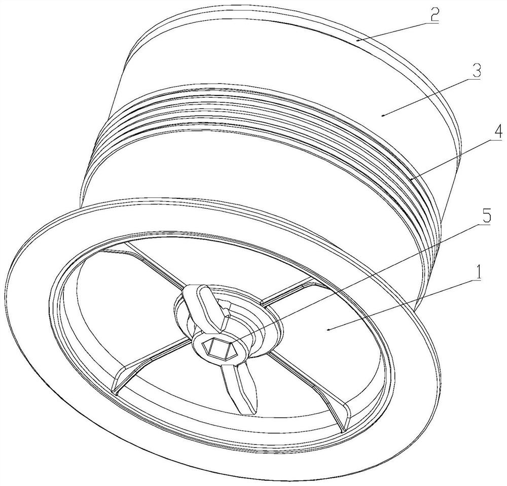
[0018] like figure 1 , figure 2 , image 3 As shown, the present invention discloses a pipe blocking device including an upper platen 1, a lower pressure plate 2, and a sealed rubber sleeve 3, and both ends of the sealing rubber sleeve 3 are connected between the upper press plate 1, the lower pressure plate 2, respectively. Four guiding columns 14 are provided between the upper platen 1 and the lower pressure plate 2, and there is a circular slider 10 on the guide column 14, and one through hole 6 is provided at the center of the upper platen 1, in the through hole 6. A rotating shaft 5 is provided in which a jam 7 is provided on the upper press plate 1 at the through hole 6, and a ring card slot 8 is provided on the rotating shaft 5 at correspond to the ree spring 7, the jam 7 card Inside the annular card groove 8, an external thread 9 is provided on the rotating shaft 5 below the annular card groove 8, and a threaded hole is provided on the circular slider 10 corresponding to th...


PUM


Abstract

The invention relates to the technical field of pipeline plugging, in particular to a pipeline plugging device. The device comprises an upper pressing plate, a lower pressing plate and a sealing rubber sleeve, the two ends of the sealing rubber sleeve are connected with the upper pressing plate and the lower pressing plate respectively, at least one guide column is arranged between the upper pressing plate and the lower pressing plate, each guide column is sleeved with a circular sliding block, a through hole is formed in the center of the upper pressing plate, a rotating shaft is arranged in the through hole, an external thread on the rotating shaft is connected with an internal thread of a threaded hole in a matched mode, a plurality of supporting frames are arranged on the periphery of the lower pressing plate in the sealing rubber sleeve in an annular array mode, and the circular sliding blocks extrude the supporting frames which are not connected with the upper pressing plate or the lower pressing plate towards the side of the sealing rubber sleeve when the rotating shaft moves in the axial direction. According to the pipeline plugging device, a pipeline can be plugged, and pressure is continuously provided for the sealing rubber sleeve by the supporting frames in the plugging process, so that the stability and continuity of the sealing effect are ensured.

Description

Technical field [0001] The present invention relates to the field of pipeline sealing technology, in particular a pipe sealing device. Background technique [0002] In the prior art, the pipe sealing device generally uses the upper press plate, the lower pressure plate is extruded, and the rubber ring of the annular structure is extruded, so that the outer diameter of the rubber ring increases, thereby realizing the inner wall of the rubber ring and the pipeline A certain pressure is generated, and the pipe is closed, and the seal between the rubber ring and the pipe can be maintained. However, under the action of the external environmental factors, the rubber produces fatigue, elasticity, etc., which causes the sealing performance between the rubber ring and the pipe to decrease, and the sealing effect of the pipe decreases. Inventive content [0003] In order to solve the above technique insufficient, the present invention provides a pipe sealing device to seal the pipe and th...

Claims


Application Information

Patent Timeline
Patent Type & Authority Applications(China)
IPC IPC(8): F16L55/10
CPCF16L55/10
Inventor 周兴林
Owner 浙江恩硕电力科技股份有限公司
Features
  • R&D
  • Intellectual Property
  • Life Sciences
  • Materials
  • Tech Scout
  • Unparalleled Data Quality
  • Higher Quality Content
  • 60% Fewer Hallucinations
Learn More