Heat storage device

A heat storage device and heat storage technology, applied in heat storage equipment, indirect heat exchangers, fluid heaters, etc., can solve problems such as space occupation and complex control

Pending Publication Date: 2021-08-31
NAT UNIV CORP TOKAI NAT HIGHER EDUCATION & RES SYST
View PDF8 Cites 0 Cited by
  • Summary
  • Abstract
  • Description
  • Claims
  • Application Information

AI Technical Summary

Problems solved by technology

[0004] However, for example, the conventional air conditioner for an electric vehicle as shown in Patent Document 1 is a large-scale device, so it not only takes up space, but also requires complicated control, so there is a problem that the whole system becomes a large-scale system.

Method used


Image

  • Heat storage device
  • Heat storage device
  • Heat storage device

Examples


Embodiment approach 1

[0028] The heat storage device according to Embodiment 1 of the present invention is a heat storage device that uses chemical heat storage and operates with air and electricity, and utilizes an oxidation-reduction reaction for temperature regulation operation in the chemical heat storage.

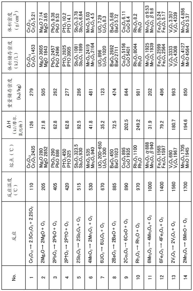
[0029] here, figure 1 It is a table showing an example of a reaction system of chemical heat storage using a redox reaction, and shows the reaction formula, reaction temperature, melting point of each substance, etc. of substances oxidized / reduced by temperature adjustment operation. In this Embodiment 1, to use figure 1 Reaction No.9 of the table shown "2Co 3 o 4 (Cobalt tetraoxide)→6CoO (cobalt monoxide)+O 2 (oxygen)" as an example.

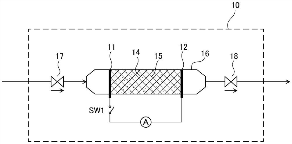
[0030] figure 2 It is a figure which schematically shows an example of the schematic structure of the heat storage device concerning Embodiment 1 of this invention. in the figure 2 In FIG. 1 , air flows into the heat storage material 14 from the lef...

Embodiment approach 2

[0060] Similar to Embodiment 1, the heat storage device according to Embodiment 2 of the present invention is a heat storage device that operates with air and electricity using chemical heat storage in which oxidation-reduction reactions for temperature adjustment operations are utilized. In this Embodiment 2, also by using figure 1 Reaction No.9 of the table shown "2Co 3 o 4 (Cobalt tetraoxide)→6CoO (cobalt monoxide)+O 2 (oxygen)" as an example.

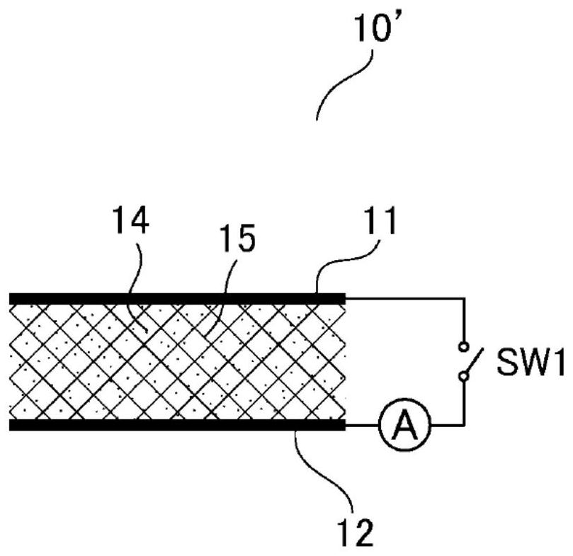
[0061] Figure 9 It is a figure which schematically shows an example of the schematic structure of the heat storage device concerning Embodiment 2 of this invention. In addition, the same code|symbol is attached|subjected to the same structure as the thermal storage device demonstrated in Embodiment 1, and the overlapping description is abbreviate|omitted. The second embodiment Figure 9 The heat storage device 20 shown is the same as that of Embodiment 1 figure 2 The heat storage device 10 shown differs in having several el...


PUM


Abstract

Provided is a heat storage device which has a simple and small shape that does not occupy a space when mounted on an electric vehicle, and which can efficiently store and dissipate heat without using water when used as a heating device. The heat storage device (10) is provided with a heat storage material (14) that is oxidized / reduced by a temperature adjustment operation; a heat transfer material (15) that heats the heat storage material (14); and at least one pair of electrodes (11, 12) that heat the heat transfer material (15) by being connected to a power source. A container (16) containing a heat storage material (14), a heat transfer material (15) and at least one pair of electrodes; an upstream-side valve (17) which is provided at an upstream-side inlet of the container (16) and which isolates the inside and outside of the container (16); and a downstream-side valve which is provided at a downstream-side outlet of the container (16) and which isolates the inside and outside of the container (16).

Description

technical field [0001] The present invention relates to heat storage devices that operate by air and electricity. Background technique [0002] Conventionally, in an engine car, the air conditioner that usually works as a mechanical compression air conditioner (air conditioner) is only for cooling, and for heating, it uses the heat of the cooling water of the engine to heat it. This is because the air conditioner cannot be used due to frost in winter, and even if the air conditioner is used, it is only up to about 10°C. When the outside temperature is below 10°C, a heater using the exhaust heat of the engine is used. [0003] In addition, in recent years, the development of electric vehicles has been carried out. For example, Patent Document 1 discloses an air conditioner for electric vehicles composed of a heat pump type air conditioning system, a heat storage type air conditioning system, and a combustion type air conditioning system as an air conditioner even at low tempe...

Claims


Application Information

Patent Timeline
Patent Type & Authority Applications(China)
IPC IPC(8): B60H1/22F28D20/00
CPCY02E60/14F28D20/003F28D2021/008B60H1/00499B60H1/2215F24H7/0216C09K5/16F28D2020/0004F28D2020/0073
Inventor 小林敬幸市濑笃博清水琢久哉
Owner NAT UNIV CORP TOKAI NAT HIGHER EDUCATION & RES SYST
Why Eureka
Try Eureka