Recording device
A technology for recording devices and recording areas, which is applied to printing devices, power transmission devices, printing, etc., and can solve problems such as reduced recording quality and large deviations
- Summary
- Abstract
- Description
- Claims
- Application Information
AI Technical Summary
Problems solved by technology
Method used
Image

Examples
Embodiment approach
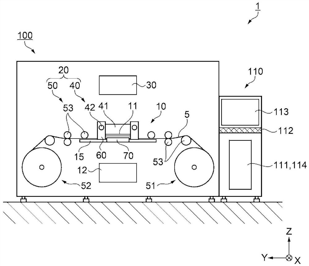
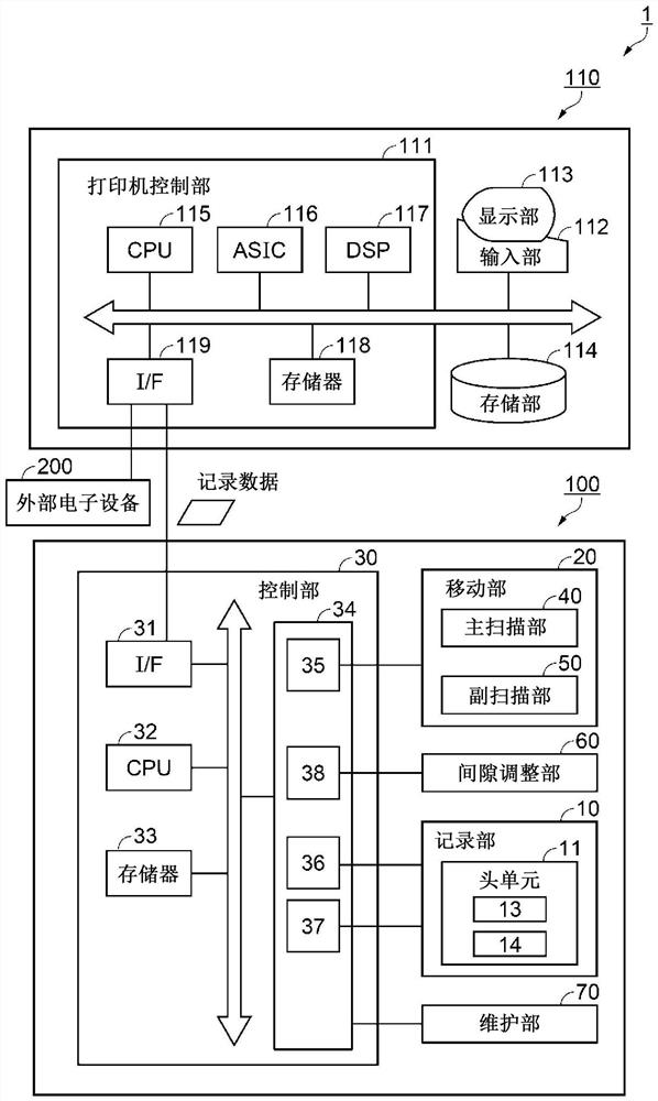
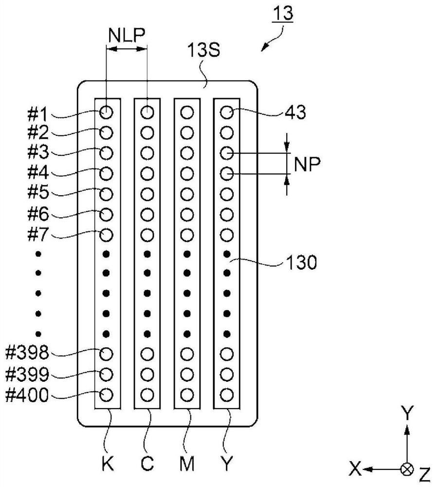
[0031] figure 1 It is a front view showing a schematic configuration of the recording device 1 according to the embodiment. figure 2 It is a block diagram showing a schematic configuration of the recording device 1 . image 3 is a schematic diagram showing an example of the arrangement of nozzles in the head 13 . Figure 4 It is an enlarged plan view of the recording unit 10 . Figure 5 It is an enlarged side view of the recording unit 10 . It should be noted, image 3 Shown is how the nozzle surface 13S of the head 13 is viewed from below. Figure 4 It shows how the recording unit 10 is viewed from above. Figure 5 It shows how the recording unit 10 is viewed along the Y axis.
[0032] First, refer to Figure 1 to Figure 5 The configuration of the recording device 1 will be described.
[0033] The recording device 1 includes a printer 100 and an image processing device 110 connected to the printer 100 . The printer 100 is an inkjet printer that records a desired ima...
example 2
[0094] Figure 15 It is an enlarged side view showing the recording unit 10 of the recording device 301 according to the second modification. The configuration of the recording device 301 according to Modification 2 will be described. In addition, the same code|symbol is attached|subjected to the same component part as embodiment, and the overlapping description is abbreviate|omitted.
[0095] The recording device 301 has an interval changing unit. Pitch Changing Sections A first pitch changing section 381 and a second pitch changing section 382 are respectively provided in the first area and the second area sandwiching the recording area PA in the main scanning direction.
[0096] The first interval changing portion 381 and the second interval changing portion 382 are provided so as to float up from the platen 15 and are disposed at positions overlapping the head 13 reciprocating in the main scanning direction when viewed from the Z-axis. The first interval changing part 3...
PUM
 Abstract
Description
Claims
Application Information
 - R&D
- Intellectual Property
- Life Sciences
- Materials
- Tech Scout
- Unparalleled Data Quality
- Higher Quality Content
- 60% Fewer Hallucinations
Browse by: Latest US Patents, China's latest patents, Technical Efficacy Thesaurus, Application Domain, Technology Topic, Popular Technical Reports.
© 2025 PatSnap. All rights reserved.Legal|Privacy policy|Modern Slavery Act Transparency Statement|Sitemap|About US| Contact US: help@patsnap.com