Laser interference measurement signal processing device and signal subdivision method

A technology for measuring signals and processing devices, which is applied in the field of laser interferometry signal processing devices, can solve the problems of increasing nonlinear errors in the processing circuit system, restricting the application of laser interferometry systems, and slow subdivision speed, etc., to achieve the elimination of signal DC components, Fast, quality-enhancing effects

Active Publication Date: 2021-11-05
HEFEI UNIV OF TECH
View PDF3 Cites 1 Cited by
  • Summary
  • Abstract
  • Description
  • Claims
  • Application Information

AI Technical Summary

Problems solved by technology

[0003] Subdivide the periodic two-way orthogonal signals output by the interferometer. If hardware subdivision is used, the higher the subdivision number, the more complex the electronic system will be. The noise in the processing circuit will increase the nonlinear error of the system; if the hardware subdivision is used Software subdivision, often using the discriminant hexagram limit and look-up table method to achieve subdivision, but to achieve high-power subdivision, it is necessary to modify the program and tangent table. This kind of software query has a slow subdivision speed, and is mainly used for low-frequency input signals. In the measurement system, the application of the laser interferometry system in real-time, high-speed and other scenarios is restricted to a certain extent

Method used


Image

  • Laser interference measurement signal processing device and signal subdivision method
  • Laser interference measurement signal processing device and signal subdivision method
  • Laser interference measurement signal processing device and signal subdivision method

Examples


Embodiment Construction

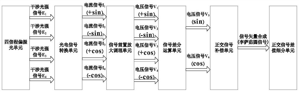
[0045] like figure 1 Shown, a kind of laser interferometry signal processing device comprises:

[0046] The quadruple-pass polarizing unit adopts a polarizing beam splitter and a λ / 4 wave plate, uses the optical path difference amplification technology to subdivide the signal by 4 times, and performs spatial phase shifting of the interference fringes to obtain four-way interference output light with a phase difference of 90° in sequence Strong signal E1, E2, E3, E4;

[0047] The photoelectric signal conversion unit uses four photodetectors to convert the four light intensity signals E1, E2, E3, E4 into four orthogonal current signals I1, I2, I3, I4 respectively;

[0048] The signal pre-amplification conditioning unit adopts the I / F conversion setting to convert the current signals I1, I2, I3, and I4 into voltage signals V1, V2, V3, and V4, and then adopts an amplifier circuit, a DC adjustment circuit, and a low voltage signal for the subsequent stage. Operational amplification...


PUM


Abstract

The invention relates to a laser interference measurement signal processing device which comprises a quadruple polarized light unit, the output end of the quadruple polarized light unit is connected with the input end of a photoelectric signal conversion unit, and the output end of the photoelectric signal conversion unit is connected with the input end of a signal pre-amplification conditioning unit. The output end of the signal pre-amplification conditioning unit is connected with the input end of the signal differential operation unit, the output end of the signal differential operation unit is connected with the input end of the orthogonal signal compensation unit, and the output end of the orthogonal signal compensation unit is connected with the input end of the orthogonal signal difference subdivision counting unit. The invention further discloses a signal subdivision method of the laser interference measurement signal processing device. The resolution ratio of the measurement system is improved by 800 times, so that the high-precision requirement of the laser interference measurement system is met, the dynamic capability of the laser interference displacement measurement system is improved, and the dynamic frequency measurement response of the system is improved from 0.1 second to 0.04 second.

Description

technical field [0001] The invention relates to the technical field of high-precision measurement, in particular to a laser interferometry signal processing device and a signal subdivision method. Background technique [0002] In order for the interferometer to achieve high-precision nanometer-level precision measurement, high resolution must first be obtained. At present, there are two main methods to improve the resolution of the interferometer: one is to subdivide the interference signal through the circuit; the other is to multiply the optical path difference. Due to factors such as the structure of the laser interferometry system, the frequency doubling of the optical path difference is limited, so the measurement accuracy to be provided depends to a large extent on the signal processing and subdivision methods. [0003] Subdivide the periodic two-way orthogonal signals output by the interferometer. If hardware subdivision is used, the higher the subdivision number, th...

Claims


Application Information

Patent Timeline
Patent Type & Authority Applications(China)
IPC IPC(8): G01B9/02G01B11/02
CPCG01B9/02083G01B11/02
Inventor 刘小为黄强先
Owner HEFEI UNIV OF TECH
Why Eureka
Try Eureka