A kind of optical signal receiving device and photoelectric detection equipment

A receiving device and technology for optical signals, applied in the field of photoelectric detection, can solve the problem of inability to reduce or remove optical basic noise, and achieve the effects of eliminating basic noise, simple circuit structure, and easy implementation.

Active Publication Date: 2020-06-26
SANGHAI YUSN INFORMATION TECH
View PDF7 Cites 0 Cited by
  • Summary
  • Abstract
  • Description
  • Claims
  • Application Information

AI Technical Summary

Problems solved by technology

[0006] In view of the shortcomings of the prior art described above, the object of the present invention is to provide an optical signal receiving device and a photoelectric detection device, which are used to solve the basic problem that the optical signal receiving device of the optical detection device in the prior art cannot reduce or remove the light itself. noise problem

Method used


Image

  • A kind of optical signal receiving device and photoelectric detection equipment

Examples


Embodiment

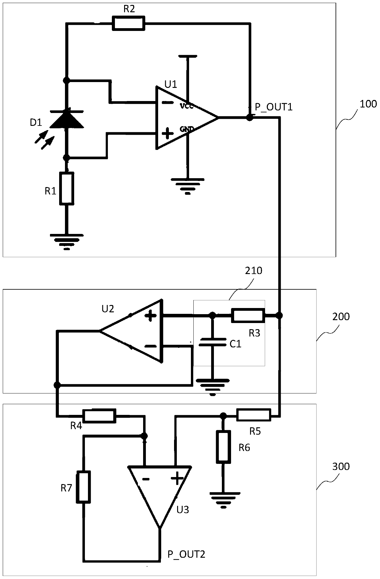
[0028] Such as figure 1 As shown, the optical signal receiving device of this embodiment includes: a current-voltage converting unit 100 , a filtering unit 200 and a signal acquiring unit 300 . Wherein, the current-to-voltage conversion unit 100 is used for receiving an optical signal and converting the received optical signal into a voltage signal. Wherein, the optical signal includes an AC component of the optical signal, a DC component of the optical signal, and an optical noise component. The AC component of the optical signal is generated by the emitted optical signal passing through the detected substance; the DC component of the optical signal is generated due to the scattering, reflection or refraction of the emitted optical signal; the optical noise component is the basic noise of the emitted optical signal. Corresponding to the optical signal, the voltage signal also includes an AC component, a DC component and a noise component; the AC component corresponds to the ...


PUM


Abstract

The invention provides an optical signal receiving device and photoelectric detection equipment. The optical signal receiving device comprises a current-voltage conversion unit, a filtering unit and asignal acquisition unit, wherein the current-voltage conversion unit is used for receiving an optical signal and converting the received optical signal into a voltage signal, and the voltage signal comprises an alternating current component, a direct current component and a noise component; the filtering unit is connected with an output end of the current and voltage conversion unit and used foracquiring the direct current component and the noise component through low-pass filtering; and the signal acquisition unit is connected with the output end of the current-voltage conversion unit and an output end of the filtering unit, and acquires the alternating current component through performing a differential operation on the voltage signal outputted by the current-voltage conversion unit and the direct current component and the noise component which are outputted by the filtering unit. The optical signal receiving device is low in cost and simple in structure, increases the stability and reliability of the output signal and improves the accuracy of the photoelectric detection equipment.

Description

technical field [0001] The invention relates to the field of photoelectric detection, in particular to an optical signal receiving device and photoelectric detection equipment. Background technique [0002] Photoelectric technology is a high-tech that closely combines traditional optical technology with modern electronic technology and computer technology. ) important means. [0003] As we all know, the existing photoelectric detection device includes a light emitting unit and a light receiving unit, and it is more common to use a laser transmitter and a laser receiver. The laser transmitter is used to transmit laser signals, and the intensity of the laser signal is controlled by the intensity of the electrical signal; the laser receiver receives the laser signal from the laser transmitter and converts it into a corresponding electrical signal according to the signal intensity of the laser signal. Each detected parameter is calculated from the intensity variation of the el...

Claims


Application Information

Patent Timeline
Patent Type & Authority Patents(China)
IPC IPC(8): G01D5/26G01D3/032
CPCG01D3/032G01D5/26
Inventor 宋戈蓝海燕谢鑫张金旺
Owner SANGHAI YUSN INFORMATION TECH
Why Eureka
Try Eureka