Novel support for releasing constraint during earthquake

A new type of bearing technology, applied in the direction of bridge parts, bridges, buildings, etc., can solve the problem that the shear pin or bolt is not accurate enough to identify the horizontal force of the earthquake, affects the realization of the shock isolation function of the bearing, and the shear pin or bolt is stressed. It is not clear and other problems, and achieves the effect of simple structure, strong practicability, limit and intelligent shock absorption and isolation.

Pending Publication Date: 2021-11-16
CHENGDU XINTU TECH +1
View PDF0 Cites 0 Cited by
  • Summary
  • Abstract
  • Description
  • Claims
  • Application Information

AI Technical Summary

Problems solved by technology

[0004] However, in this structure, the shear pin or bolt force is often not clear, and the shear pin or bolt is not accurate enough to identify the seismic horizontal force, which may affect the realization of the shock absorption and isolation function of the support.

Method used


Image

  • Novel support for releasing constraint during earthquake
  • Novel support for releasing constraint during earthquake
  • Novel support for releasing constraint during earthquake

Examples


Embodiment 1

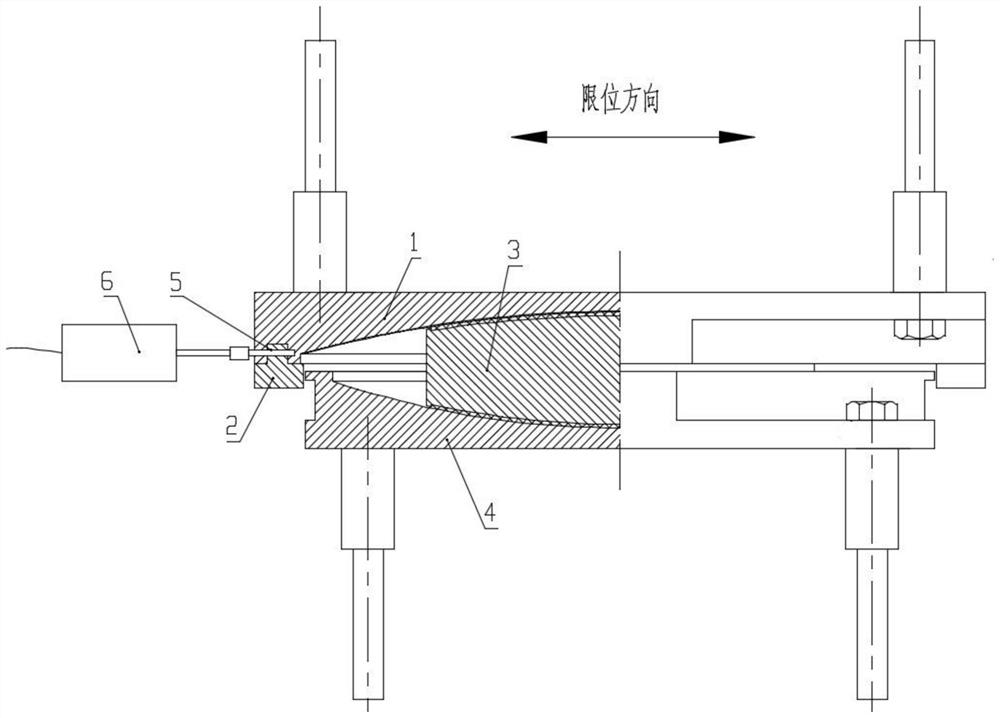
[0039] Such as Figure 1-Figure 3 Shown; A kind of new type of support that restraint releases when earthquake occurs, comprises upper support plate 1, middle support plate 3, lower support plate 4 that are arranged in turn from top to bottom; Said upper support plate 1 and The first friction pair is formed between the middle support plates 3, the second friction pair is formed between the middle support plate 3 and the lower support plate 4; Connected Constraint Drive Mechanism 6. .

[0040] Under normal working conditions, the upper support plate 1 and the restraining block are restrained in the horizontal direction and vertical direction, wherein the restraint in the horizontal direction is controlled by the structure at the junction of the two; while the restraint in the vertical direction is controlled by the restraint drive mechanism 6 to restrain;

[0041] When an earthquake occurs, the restraint driving mechanism 6 operates to release the vertical restraint of the u...
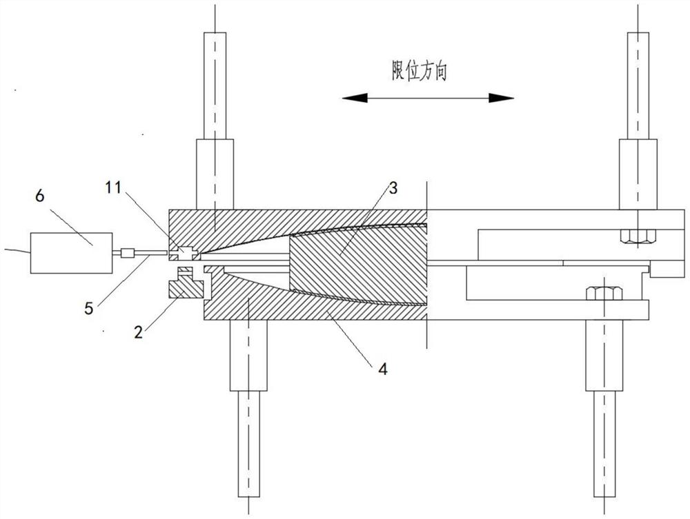
Embodiment 2

[0064] The difference between this embodiment and Embodiment 1 is that the installation position of the constraint block is different. In this embodiment, the constraint block will be installed on the lower support plate 4, wherein the second stopper is located on the lower support plate 4 close to the upper support In the groove on one side of the plate 1, and fix it with the lower support plate 4 through the limit pin 2;

[0065] When an earthquake occurs, the earthquake early warning system transmits signals to the active earthquake identification device in advance, which causes the trigger mechanism to actuate, and the trigger mechanism releases the vertical constraint between the stopper 2 and the lower support plate 4, thereby releasing the upper support plate 1 and the lower support plate 4. The restraint of the middle support plate 3 realizes the function of releasing displacement or shock absorption and isolation.

[0066] Embodiment 1 and Embodiment 2 are different f...


PUM


Abstract

The invention relates to the technical field of bridge seismic mitigation and isolation, and particularly discloses a novel support for relieving constraint during earthquake. The novel support comprises an upper support plate, a middle support plate and a lower support plate which are sequentially arranged from top to bottom, a first friction pair is formed between the upper support plate and the middle support plate, and a second friction pair, a restraining block located at the bottom of the upper support plate and used for limiting relative displacement of the upper support plate and the middle support plate, and a restraining driving mechanism connected with the restraining block are formed between the middle support plate and the lower support plate. Limiting constraint can be actively released when an earthquake occurs, and the earthquake reduction and isolation function is achieved through the pendulum effect of the middle support plate.

Description

technical field [0001] The invention relates to the technical field of shock absorption and isolation of bridges, and more specifically, relates to a new type of support that is released from constraints when an earthquake occurs. Background technique [0002] The bridge support is an important part connecting the upper girder body and the lower pier. It can transmit the reaction force and deformation (displacement and rotation angle) of the upper structure to the lower structure. For the support to bear the force in the horizontal direction, it often uses a stopper to resist the horizontal force. In the seismic-isolation bearing system, when an earthquake occurs, the restraint in the horizontal direction of the bearing is the main condition that limits whether it can realize the seismic-isolation function. [0003] At present, shear pins or bolts are often used to connect the block to the shock-absorbing and isolating support to release the horizontal constraint. The cons...

Claims


Application Information

Patent Timeline
Patent Type & Authority Applications(China)
IPC IPC(8): E01D19/04
CPCE01D19/048
Inventor 邱廷琦刘海亮张启帆刘成骆明成陈宏兰鹏
Owner CHENGDU XINTU TECH
Why Eureka
Try Eureka