Efficient digital broadcast television transmitting equipment
A technology of digital broadcast TV and transmitting equipment, which is applied in the direction of TV, color TV, color TV parts, etc. It can solve the problems that the signal device is not easy to disassemble and maintain, the direction of the launch cannot be adjusted, and the internal air is not convenient to dry, etc., so as to improve The effect of tension, increasing the contact area, and reducing the occupation of internal space
- Summary
- Abstract
- Description
- Claims
- Application Information
AI Technical Summary
Problems solved by technology
Method used
Image
Examples
Embodiment 1
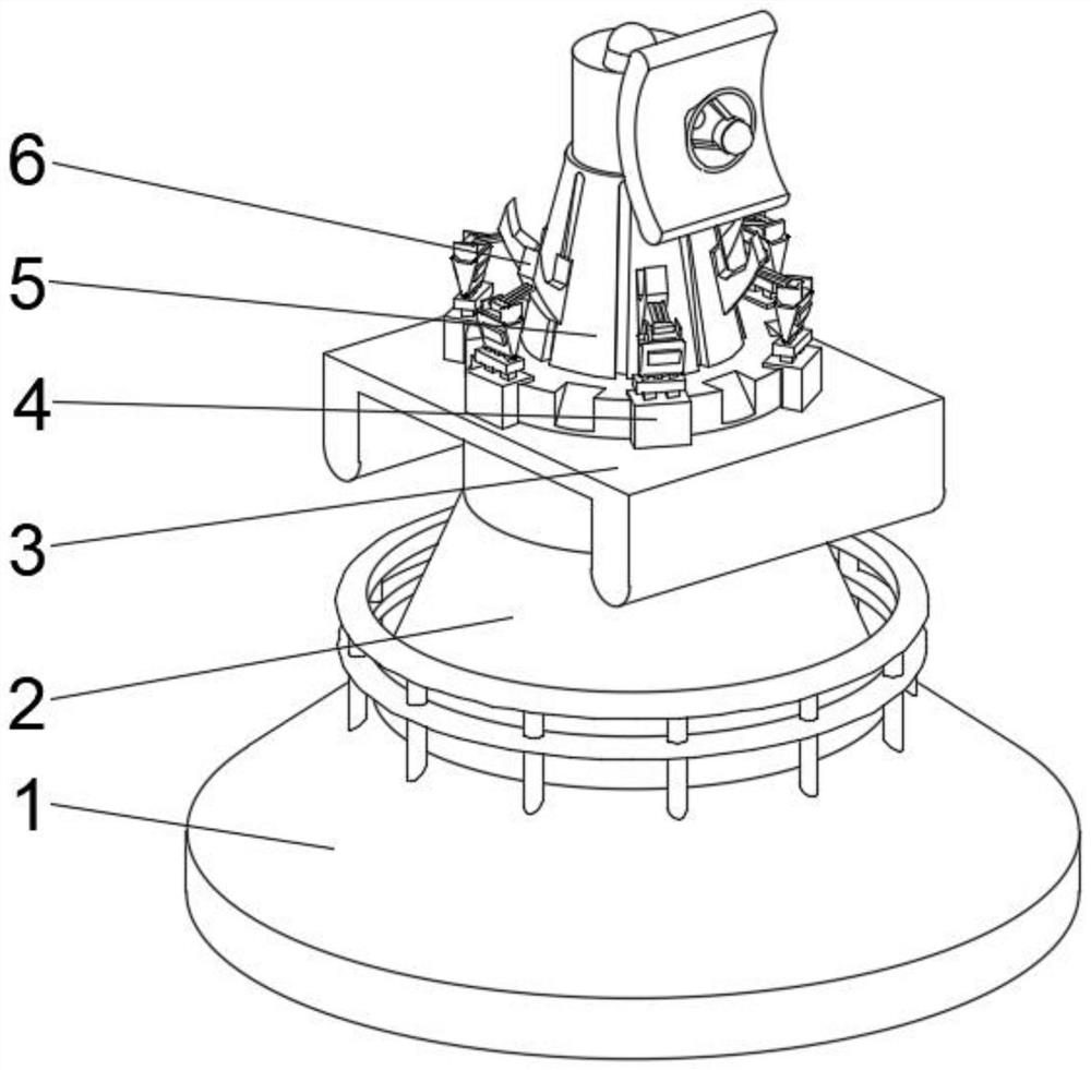
[0032] see Figure 1-2 , the present invention provides a technical solution: a high-efficiency digital radio and television transmitting equipment, including a fixed base 1, a rotating base 2 is arranged on the top of the fixed base 1, a transition platform 3 is fixedly connected to the top of the rotating base 2, and the transition platform 3 The middle position of the top of the platform is fixedly connected with the working device 5, the top of the transition platform 3 is fixedly connected with the adjustment frame 4 on both sides of the working device 5, and the top of the adjustment frame 4 is fixedly connected with the balance connecting block 6 on the side close to the working device 5 .
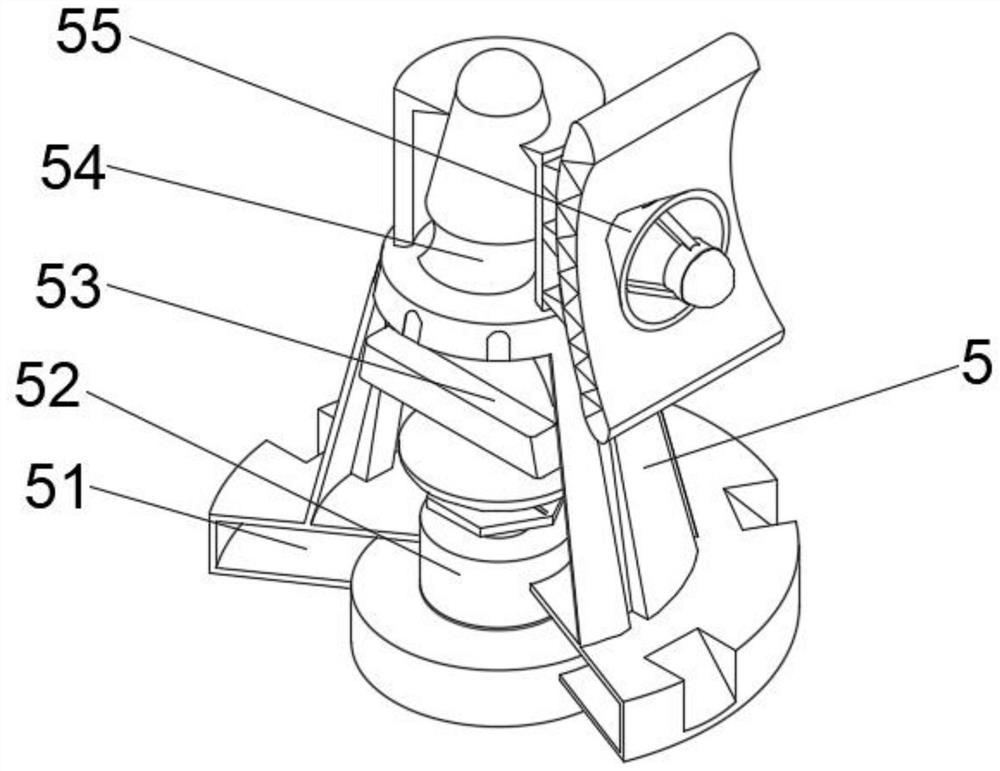
[0033] Among them, the first component of the working device 5 includes a fixed main body 51, an auxiliary mechanism 52 is provided at the middle of the bottom of the inner cavity of the fixed main body 1, and a cooling mechanism 53 is fixedly connected to the top of the inner wall ...
Embodiment 2
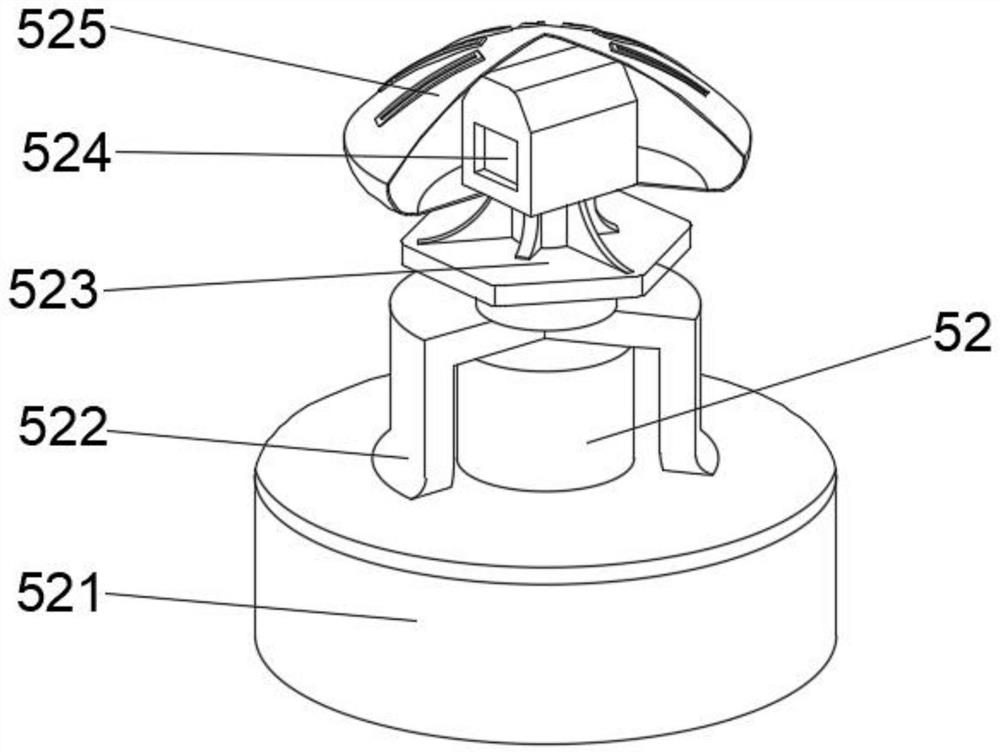
[0036] see Figure 1-4On the basis of Embodiment 1, the present invention provides a technical solution: Component 1 of the auxiliary mechanism 52 includes an auxiliary block 521, the top of the auxiliary block 521 is fixedly connected with a support body 522, and the top middle position of the support body 522 is fixedly connected with a The stable frame 523, the top of the stable frame 523 is fixedly connected with the isolation case 525, and the middle position of the inner cavity bottom of the isolation case 525 is fixedly connected with the data collector 524.
[0037] Wherein, the component one of the cooling mechanism 53 includes a protective cover 531, the middle position of the inner cavity bottom of the protective cover 531 is fixedly connected with a carrier 532, and the inner cavity bottom of the protective cover 531 is located at both sides of the carrier 532 and fixedly connected with a positioning auxiliary plate 533 The top of the inner wall on both sides of th...
Embodiment 3
[0040] see Figure 1-6 , on the basis of Embodiment 1 and Embodiment 2, the present invention provides a technical solution: component 2 of the auxiliary mechanism 52 includes a counterweight d1, and a positioning support body d3 is provided at the middle position of the top of the counterweight d1, and the positioning support The top of the body d3 is fixedly connected with the signal booster d5, the top of the counterweight d1 is fixedly connected with the top plate d2 on both sides of the positioning support body d3, and the middle position of the top of the top plate d2 is fixedly connected with the fastening plate d4.
[0041] Wherein, the second component of the cooling mechanism 53 includes a force plate t1, the top of the force plate t1 is fixedly connected with a feedback seat t2, the top of the feedback seat t2 is fixedly connected with a radiator t4, and the middle position of the top of the radiator t4 is fixedly connected with a suction The heating element t5 and ...
PUM
 Abstract
Description
Claims
Application Information
 - R&D
- Intellectual Property
- Life Sciences
- Materials
- Tech Scout
- Unparalleled Data Quality
- Higher Quality Content
- 60% Fewer Hallucinations
Browse by: Latest US Patents, China's latest patents, Technical Efficacy Thesaurus, Application Domain, Technology Topic, Popular Technical Reports.
© 2025 PatSnap. All rights reserved.Legal|Privacy policy|Modern Slavery Act Transparency Statement|Sitemap|About US| Contact US: help@patsnap.com


