Dehydration equipment for food waste treatment
A technology of food waste and dehydration equipment, which is applied in the direction of chemical instruments and methods, solid waste removal, transportation and packaging, etc., can solve the problems of poor extrusion effect of food waste and slow processing speed of food waste, and achieve high efficiency Improved effect
- Summary
- Abstract
- Description
- Claims
- Application Information
AI Technical Summary
Problems solved by technology
Method used
Image
Examples
Embodiment 1
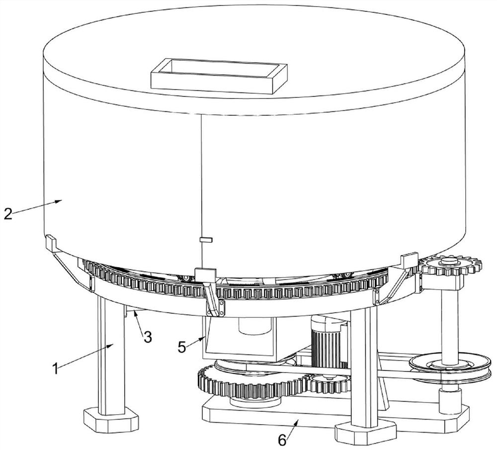
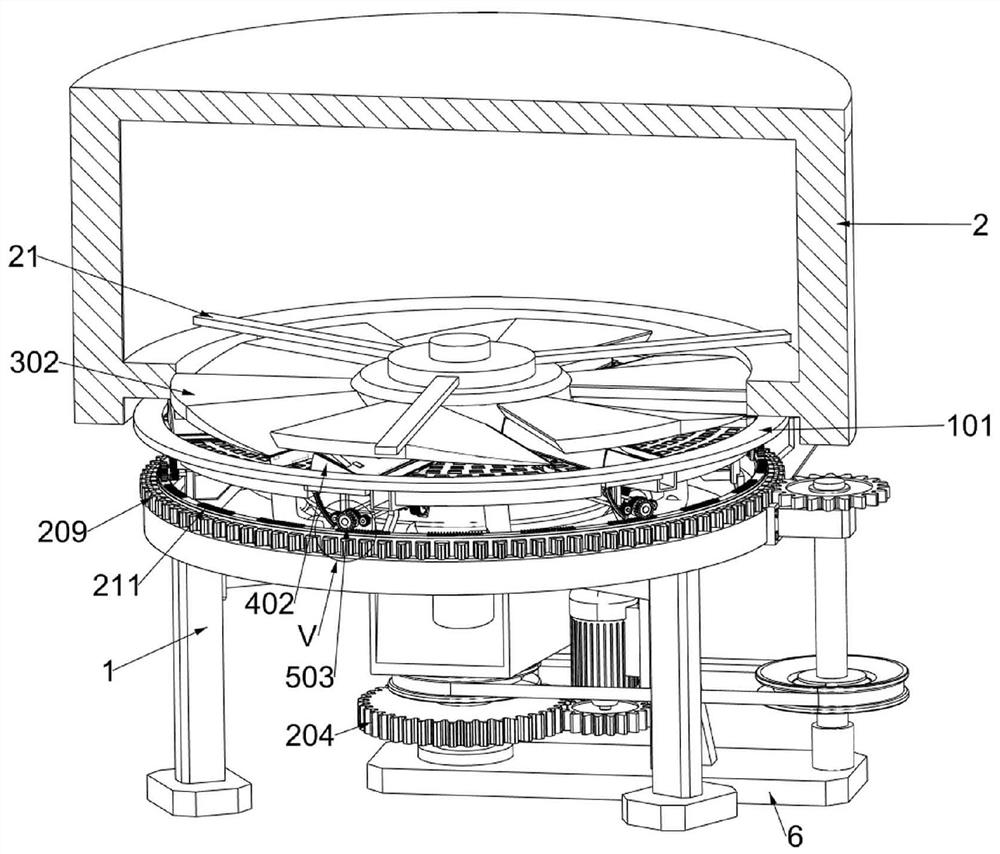
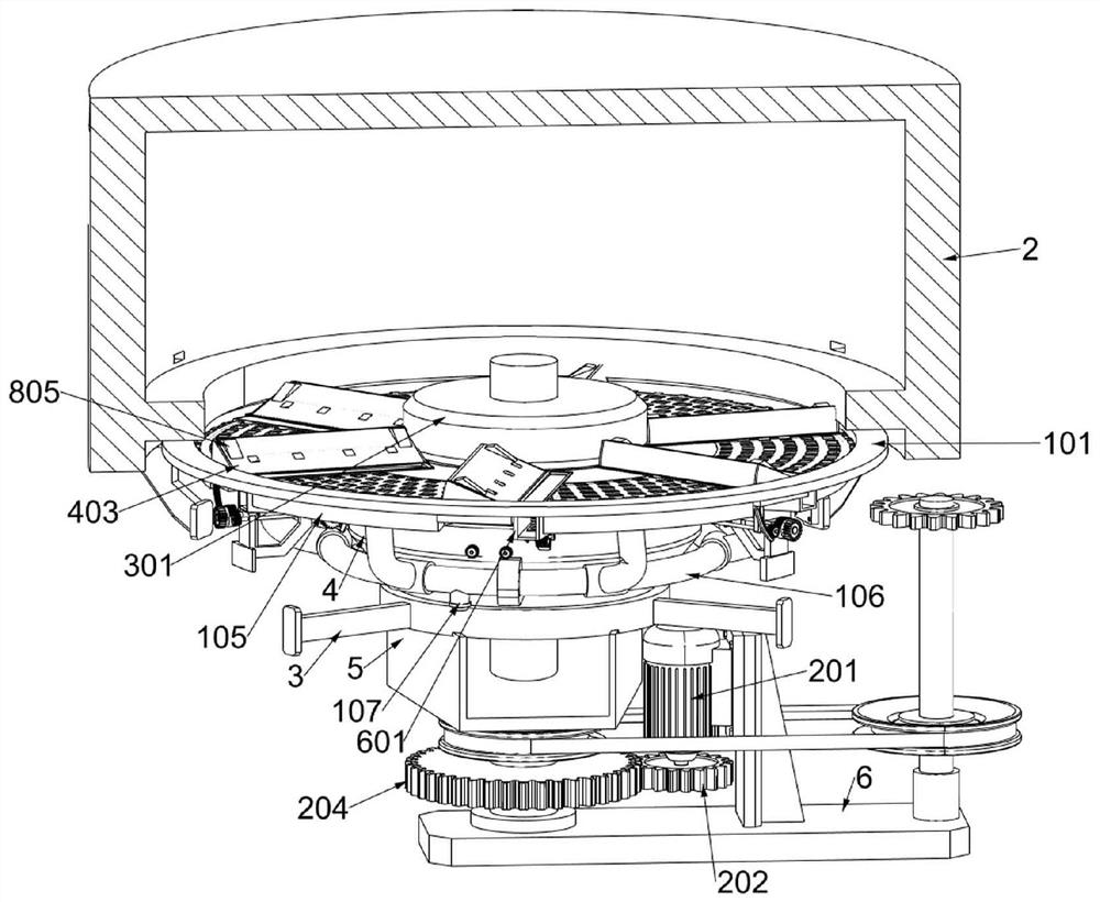
[0036] A kind of dehydration equipment for meal waste treatment, such as Figure 1-3 As shown, it includes waste liquid collection unit, main power transmission unit, diversion unit, extrusion unit, intermittent power transmission unit, unloading unit, external support frame 1, shell 2, internal fixing frame 21, internal support frame 3, collecting Bucket 4, discharge plate 5 and bottom fixing plate 6; the upper part of the external support frame 1 is connected with the shell 2; the inner side of the shell 2 is fixedly connected with the internal support frame 21; The middle part of the support frame 3 is connected with a collection bucket 4; the lower part of the collection bucket 4 is connected with a discharge plate 5; the lower part of the external support frame 1 is connected with a bottom fixing plate 6; the inner lower part of the shell 2 is connected with a waste liquid collection unit; the waste liquid The lower part of the collection unit is connected to the collecti...
Embodiment 2
[0049] On the basis of Example 1, such as Figure 11 As shown, an auxiliary closing unit is also included, the extrusion unit is provided with an auxiliary closing unit, and the auxiliary closing unit includes a second bracket 701, an eighth rotating shaft 702, a seventh spur gear 703 and a second arc gear rod 704; From a top view, two second brackets 701 are fixedly connected to each clockwise side of the six first carrier boards 405; two adjacent second brackets 701 are rotatably connected to an eighth shaft 702; six eighth shafts 702 A seventh spur gear 703 is affixed to both ends; a second arc-shaped tooth bar 704 is affixed to the bottom of each first side plate 402; the adjacent seventh spur gear 703 and the second arc-shaped tooth bar 704 mesh with each other.
[0050] If it is necessary to increase the squeezing force of the garbage, it is necessary to increase the stiffness coefficient of the first elastic member 406, so that when the moving extrusion plate 303 pushe...
Embodiment 3
[0053] On the basis of Example 2, such as Figure 8 As shown, a tail plate unit is also included. The extrusion plate 303 is provided with a tail plate unit. The tail plate unit includes a tail fixing plate 801, a ninth rotating shaft 802, a tail pushing plate 803, a third elastic member 804 and a flat pushing plate 805. ; Viewed from a top view, each of the counterclockwise sides of the six extruding plates 303 is fixedly connected with a tail fixing plate 801; each of the lower surfaces of the six tail fixing plates 801 is rotatably connected with a ninth rotating shaft 802; the six ninth rotating shafts Each of the middle parts of 802 is fixed with a tail push plate 803; two third elastic members 804 are respectively fixed between the adjacent tail fixing plate 801 and the tail push plate 803; the upper surfaces of the six pressure plates 403 are respectively fixed. Two flat push plates 805 are connected.
[0054] When the extrusion plate 303 and the pressure receiving pla...
PUM
 Abstract
Description
Claims
Application Information
 - R&D
- Intellectual Property
- Life Sciences
- Materials
- Tech Scout
- Unparalleled Data Quality
- Higher Quality Content
- 60% Fewer Hallucinations
Browse by: Latest US Patents, China's latest patents, Technical Efficacy Thesaurus, Application Domain, Technology Topic, Popular Technical Reports.
© 2025 PatSnap. All rights reserved.Legal|Privacy policy|Modern Slavery Act Transparency Statement|Sitemap|About US| Contact US: help@patsnap.com


