Flow control anti-deadlock method and device based on priority

A flow control and priority technology, applied in the field of communication, can solve problems such as PFC deadlock, and achieve the effect of avoiding message loss and PFC deadlock

Pending Publication Date: 2021-12-31
ZTE CORP
View PDF0 Cites 2 Cited by
  • Summary
  • Abstract
  • Description
  • Claims
  • Application Information

AI Technical Summary

Problems solved by technology

[0007] Embodiments of the present invention provide a PFC deadlock prevention method and device to at least solve the problem of PFC deadlock in a network generating a micro-loop in the related art

Method used


Image

  • Flow control anti-deadlock method and device based on priority
  • Flow control anti-deadlock method and device based on priority
  • Flow control anti-deadlock method and device based on priority

Examples


Embodiment 1

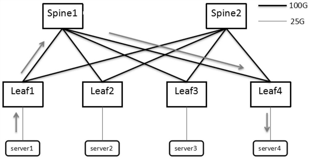
[0106] This embodiment is PFC deadlock prevention in a single Pod networking topology. Link faults lead to rerouting, that is, valley routing occurs between spine-leaf-spine. When the conditions are met, a micro-loop is formed first, and the CBD is further formed, which may eventually lead to PFC deadlock. In this embodiment, the implementation method of the present invention can be used to avoid the occurrence of PFC deadlock in advance.

[0107] Figure 10 is a schematic diagram of traffic before a link failure in a single pod network architecture according to an embodiment of the present invention, as shown in Figure 10 As shown, before the link failure, there are four flows flow1, flow2, flow3, flow4, and the four flows are respectively mapped to the priority queue 3 (virtual channel 3) of the corresponding port, Flow1: C2③ (that is, switching device C, port 2 Priority queue 3)-->B4③-->B3③-->F2③; Flow2: D2③-->B1③-->B2③-->E2③; Flow3: E1③-->A3③-->A2③-->D1③ ;Flow4: F1③-->...

Embodiment 2

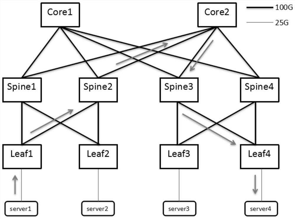
[0131] This embodiment is the PFC deadlock prevention of cross-Pod networking topology. Link faults lead to rerouting, that is, valley routing occurs between core-spine-core. When the conditions are met, a micro-loop is formed first, and the CBD is further formed, which may eventually lead to PFC deadlock. In this embodiment, the implementation method of the present invention can be used to avoid the occurrence of PFC deadlock in advance.

[0132] Figure 16 is a schematic diagram of traffic before a link failure in a cross-pod network architecture according to an optional embodiment of the present invention, such as Figure 16 As shown, before the link failure, there are four flows flow1, flow2, flow3, flow4, and the four flows are respectively mapped to the priority queue 3 (virtual channel 3) of the corresponding port, Flow1: C2③-->B4③-->B3③ -->F2③; Flow2: D2③-->B1③-->B2③-->E2③; Flow3: E1③-->A3③-->A2③-->D1③; Flow4: F1③-->A4③-->A1③-- >C1③. Here C2③ represents the priorit...


PUM


Abstract

The embodiment of the invention provides a flow control anti-deadlock method and device based on priority. The method comprises the following steps: switching equipment monitors whether a micro loop exists in a virtual channel of a CLOS network or not; when the micro-loop exists in the virtual channel, the switching equipment monitors whether the micro-loop is congested or not; and when the micro loop is congested, the speed of the flow in the micro loop is reduced. According to the invention, when the micro-loop in the network is congested, PFC deadlock can be avoided by reducing the speed of the flow in the micro-loop, so that the problem of PFC deadlock in the network for generating the micro-loop in the related technology is solved, and the effects of avoiding PFC deadlock and avoiding message loss caused by deadlock are achieved.

Description

technical field [0001] Embodiments of the present invention relate to the field of communication technologies, and in particular, to a priority-based flow control (Priority-based Flow Control, PFC) anti-deadlock method and device. Background technique [0002] Currently, the typical topology of a large data center is a leaf-spine structure. figure 1 It is a topology diagram of a single pod (point of delivery) scenario network based on related technologies. figure 2 It is a topology diagram of cross-pod scenario networking based on related technologies, such as figure 1 and figure 2 As shown, in a stable state, there is no routing loop in the data center network of the CLOS architecture, that is, without any link failure or traffic engineering, the transmission path of traffic in the data center is usually: In a single pod scenario Usually it does not pass through two spine switches, and usually does not pass through two core switches in a multi-pod scenario. [0003] I...

Claims


Application Information

Patent Timeline
Patent Type & Authority Applications(China)
IPC IPC(8): H04L12/801H04L12/825H04L12/851H04L12/931
CPCH04L47/24H04L47/25H04L47/12H04L49/557H04L49/70
Inventor 任明艳
Owner ZTE CORP
Why Eureka
Try Eureka