Ultrasonic and piezoelectric touch device and intelligent terminal

A touch device, ultrasonic technology, applied in the direction of electrical digital data processing, instruments, user/computer interaction input/output, etc., can solve problems such as failure, vibration sensitivity drop, easy to produce false touches, etc.

Pending Publication Date: 2022-01-07
GEER TECH CO LTD
0 Cites 0 Cited by

AI-Extracted Technical Summary

Problems solved by technology

[0002] At present, the touch detection solutions on the market are mainly capacitive touch solutions, but the capacitive touch solutions cannot achieve vibration feedback, and are prone to the risk of false touch
Although the pressure-sensitive button technology can realize vibration feedback and avoid the risk of false touch, the disadvantage of the pressure-sensitive button technology is that it must be ...

Method used

In a specific embodiment of the present invention, as shown in Figure 6, piezoelectric vibration module 12 is fixedly connected on housing 10, and ultrasonic transmitting module 110 and ultrasonic wave receiving module 111 are all arranged on piezoelectric vibration module 12, The ultrasonic transmitting module 110 is connected with the ultrasonic receiving module 111 and the piezoelectric vibration module 12, and the projection of the midpoint of the connecting line between the ultrasonic transmitting module 110 and the ultrasonic receiving module 111 on the housing 10 is at the center of the piezoelectric vibration module 12. The projections on the housing 10 overlap, so the center of the piezoelectric vibration module 12 corresponds to the center of vibration and the center of the ultrasonic transceiver module 11, that is, the touch detection corresponding to the midpoint of the line connecting the centers of the ultrasonic transmitting module 110 and the ultrasonic receiving module 111 The center is consistent, which is conducive to the improvement of vibration.
In another embodiment of the present invention, as shown in Figure 7, the piezoelectric vibration module 12 is supported and fixed on the housing 10, and the ultrasonic transmitting module 110 and the ultrasonic receiving module 111 are positioned under the piezoelectric vibration module 12 , and not in contact with the piezoelectric vibration module 12, the projection of the midpoint of the line connecting the centers of the ultrasonic transmitting module 110 and the ultrasonic receiving module 111 on the housing 10 coincides with the projection of the center of the piezoelectric vibration module 12 on the housing 10 . Specifically, the piezoelectri...

Abstract

The invention relates to the technical field of touch control, and particularly discloses an ultrasonic and piezoelectric touch control device and an intelligent terminal. The device comprises a shell, an ultrasonic receiving module, an ultrasonic transmitting module, a piezoelectric vibration module and a control module, wherein the control module is connected with the ultrasonic receiving module, the ultrasonic transmitting module and the piezoelectric vibration module, and the ultrasonic receiving module, the ultrasonic transmitting module and the piezoelectric vibration module are arranged on the shell; and the ultrasonic receiving module and the ultrasonic transmitting module are arranged close to the piezoelectric vibration module. The defects that a conventional capacitive touch control scheme does not have physical vibration feedback and a pressure-sensitive key can only be pressed are overcome, the experience of vibration feedback during touch can be provided for a user, and the operation effect similar to that of a real physical key is achieved.

Application Domain

Input/output for user-computer interactionGraph reading +1

Technology Topic

EngineeringElectrical and Electronics engineering +2

Image

  • Ultrasonic and piezoelectric touch device and intelligent terminal
  • Ultrasonic and piezoelectric touch device and intelligent terminal
  • Ultrasonic and piezoelectric touch device and intelligent terminal

Examples

  • Experimental program(1)

Example Embodiment

[0031] Next, the technical solutions in the embodiments of the present invention will be described in the following examples, and the described embodiments are merely, not all of the embodiments of the present invention. Based on the embodiments of the present invention, all other embodiments obtained by those of ordinary skill in the art are in the range of the present invention without making creative labor premise.
[0032] It should be noted that all directional instructions (such as above, lower, left, right, front, and post, ...) are only used in a particular attitude (as shown in the accompanying drawings). The relative positional relationship, movement conditions, etc., if the specific posture changes, the directional indication is also changed accordingly.
[0033] Further, as described in the present invention, as described in the description of "first", "second", etc., is only used to describe purposes, and cannot be understood as an indication or implies its relative importance or implicitting the number of techniques indicated. Thus, the features of "first", "second" are defined, and at least one of the features may be indicated or implicitly. In the description of the invention, the meaning of "plurality" is at least two, such as two, three, etc., unless otherwise specifically defined.
[0034] In the present invention, the term "connection", "fixed", etc. It is a mechanical connection or an electrical connection; it can be directly connected, or the intermediate medium can be indirectly connected, which may be in connection with the interior of the two components or the interaction relationship between the two elements, unless otherwise specified. The specific meaning of the above terms in the present invention can be understood in terms of specific cases.
[0035] Further, the technical solutions between the various embodiments of the present invention can be combined with each other, but must be based on those of ordinary skill in the art, and when combined with each other or cannot be implemented, it should be considered when the combination of technical solutions cannot be implemented. There is no existence, nor is it within the scope of the claims.
[0036] The technical solution of the present invention will be described in detail below in conjunction with specific embodiments.
[0037] Please refer to Figure 1-7 The embodiment of the present invention provides an ultrasonic wave and a piezoelectric touch device 100, including housing 10, ultrasonic receiving module 111, ultrasonic emission module 110, piezoelectric vibration module 12, and ultrasonic receiving module 111, ultrasonic emission module 110 The control module connected to the piezoelectric vibration module 12, wherein the ultrasonic receiving module 111, the ultrasonic transmission module 110, and the piezoelectric vibration module 12 are disposed on the housing 10, the ultrasonic receiving module 111, the ultrasonic transmitting module 110 is approaching piezoelectric vibration Module 12 is set.
[0038] In an embodiment, the housing 10 has an upper surface and the lower surface, the ultrasonic transmission module 11 ultrasonic transmitting module 110 and the ultrasonic receiving module 111 can be integrated into integrated modules, ultrasonic transmission and receiving module 11, and piezoelectric electricity The vibration module 12 is fixed to the upper surface of the housing 10.
[0039] Specifically, the ultrasonic transceiver module 11 in the present embodiment can achieve touch detection, and the piezoelectric vibration module 12 can realize vibration feedback, by providing an ultrasonic transmission module 11, the setting of the piezoelectric vibration module 12 can be provided to the user touch when vibration feedback Experience, achieved the operational effect similar to the true physical buttons, solved the shortcomings of the previous capacitive touch scheme without physical vibration feedback and the pressure-sensitive button can only press the shortcomings.
[0040] It is worth mentioning that the piezoelectric vibration module 12 used by the present embodiment can be touched, pressed, depth pressing, and the like input effect, and can be based on the linear output result to the control module according to the pressing force, to achieve various strengths. Pressing multi-level vibration feedback effect.
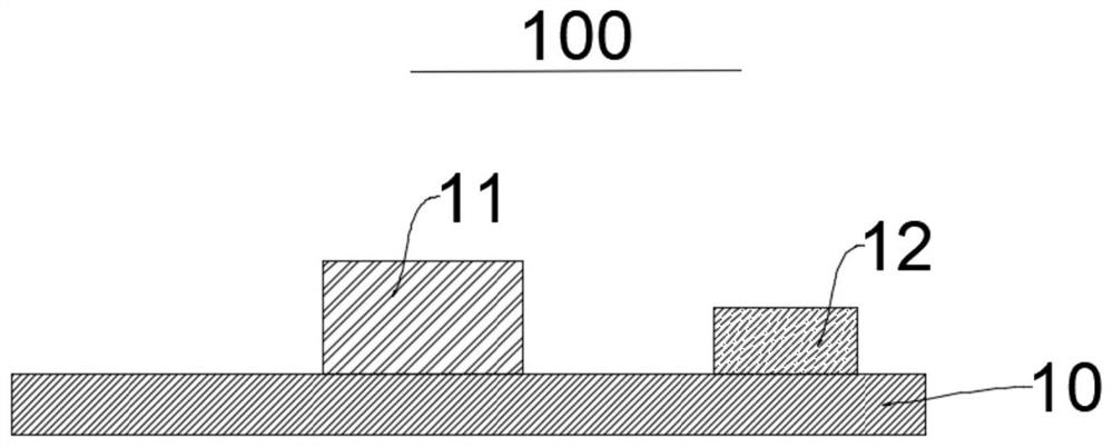
[0041] In one embodiment of the invention, if figure 1 As shown, the ultrasonic transceiver module 11 is located on one side of the piezoelectric vibration module 12. At this time, the center of the piezoelectric vibration module 12 is deviated from the touch detection center of the ultrasonic transceiver module 11, so the center corresponding to the center of the piezoelectric vibration module 12 corresponds to the center of the ultrasonic transceiver module 11 corresponding to the center of contact detection center. Dialect, the vibration feedback experience during the user's touch is slightly poor.
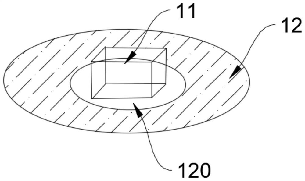
[0042] In another embodiment of the present invention, the piezoelectric vibration module 12 is a cyclic structure, and the ultrasonic transmission module 11 is located inside the annular structure, specifically, the center of the ultrasonic transceiver module 11 is coincident with the center of the annular structure. The piezoelectric vibration module 12 may be a circular ring, an elliptical ring shape, a rectangular annular, a triangular cyclic, and is not specifically defined herein.
[0043] In a specific embodiment, such as figure 2 As shown, the piezoelectric vibration module 12 is a circular ring shape. The central position of the piezoelectric vibration module 12 has a hollow portion 120, and the ultrasonic transmission module 11 is in the hollow portion 120, and the center of the piezoelectric vibration module 12 is coincident with the center of the ultrasonic transmission module 11, so the center of the piezoelectric vibration module 12 corresponds to the center. The vibration center is coincident with the touch detection center corresponding to the center of the ultrasonic transceiver module 11, at this time, the vibration experience is better.
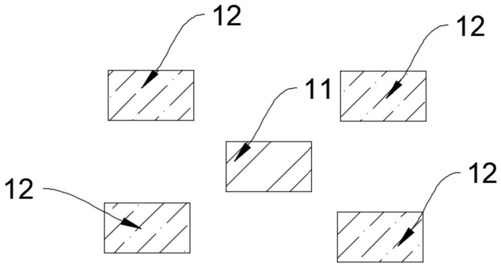
[0044] In another embodiment of the invention, the piezoelectric vibration module 12 includes a plurality of piezoelectric vibration module 12, using an array mode distribution, an array of arrays composed of a plurality of piezoelectric vibration modules 12, and ultrasonic waves. The center of the transceiver module is coincident. Specifically, such as image 3 As shown, the 4 pressure vibration module 12, and the voltage resonance module 12 can be provided with an array mode around the ultrasonic transmission module 11, the array integral center and the center of the ultrasonic transmission module 11, and the center of the ultrasonic transmission module 11. Therefore, the integral center of the array integral center of the plurality of piezoelectric vibration module 12 is coincident with the touch detection center corresponding to the center of the ultrasonic transmission module 11, at this time, the vibration experience is preferably, while also reduces the cost of the device.
[0045] In some other embodiments, such as Figure 4 As shown, the ultrasonic transmitting module 110 and the ultrasonic receiving module 111 are modules that are independent of each other. The ultrasonic transmitting module 110, the ultrasonic receiving module 111, and the piezoelectric vibration module 12 are fixed to the housing 10, and the ultrasonic emission module 110 is located between the piezoelectric vibration module 12 and the ultrasonic receiving module 111. At this time, the center of the electrical vibration module 12 is deviated from the center of the ultrasonic transmission module 11, and the ultrasonic transmission module 11, and thus the center corresponding to the center of the piezoelectric vibration module 12 and the ultrasonic transmission module 11 The center corresponding to the touch detection center is deviated and the vibration experience is slightly poor.
[0046] In another embodiment of the invention, the ultrasonic transmission module 110 and the ultrasonic receiving module 111 are modules that are independent of each other, and the underside and pressure of the ultrasonic emission module 110 and the central connection of the ultrasonic receiving module 111 on the housing 10 The center of the electrochannel module 12 coincides with the projection of the housing 10.
[0047] In an embodiment of the invention, if Figure 5 As shown, the piezoelectric vibration module 12 is located between the ultrasonic emission module 110 and the ultrasonic receiving module 111. The ultrasonic transmitting module 110 and the center connection of the ultrasonic receiving module 111 have a mid point, and the midpoint of the projection of the housing 10 is coincident with the center of the piezoelectric vibration module 12 on the housing 10. That is, the center of the piezoelectric vibration module 12 is consistent with the center position of the ultrasonic transmission module 11, so the center corresponding to the center of the piezoelectric vibration module 12 is consistent with the touch detection center corresponding to the center of the ultrasonic transmission module 11. It is conducive to improving the vibration experience.
[0048] In an embodiment of the invention, if Image 6 As shown, the piezoelectric vibration module 12 is fixed to the casing 10, and the ultrasonic transmission module 110 and the ultrasonic receiving module 111 are provided on the piezoelectric vibration module 12, and the ultrasonic transmission module 110 is in contact with the ultrasonic receiving module 111 and the piezoelectric vibration module 12. Connecting, the middle point of the ultrasonic transmission module 110 and the center connection of the ultrasonic receiving module 111 is coincident on the projection of the housing 10 and the center of the piezoelectric vibration module 12 on the housing 10, so the center of the piezoelectric vibration module 12 The corresponding vibration center and the center of the ultrasonic transmission module 11 are consistent with the touch detection center corresponding to the midpoint of the ultrasonic transmission module 110 and the central connection of the ultrasonic receiving module 111, which is advantageous for the lifting of the vibration.
[0049] In another embodiment of the invention, such as Figure 7 As shown, the piezoelectric vibration module 12 is supported on the housing 10, and the ultrasonic transmitting module 110 is located below the piezoelectric vibration module 12, and is not in contact with the piezoelectric vibration module 12, and the ultrasonic emission module 110 is The center of the ultrasonic receiving module 111 coincides with the projection of the projection of the housing 10 to the center of the piezoelectric vibration module 12 in the housing 10. Specifically, the piezoelectric vibration module 12 is fixed to the reinforcing plate 13, and then the reinforcing plate 13 is supported on the housing 10 by a screw 14. Specifically, on the one hand, the effect of the ultrasonic touch, the other hand, the piezoelectric vibration module 12 and the ultrasonic emission module 110, the interference between the ultrasonic receiving module 111 is relatively small, avoiding the vibration of the piezoelectric vibration module 12 to transmit the ultrasonic transmission Interference caused by module 110, ultrasonic receiving module 111. At the same time, the center of the pressure restriction module 12 and the center of the ultrasonic transmission module 11 are in the middle of the ultrasonic transmission module 11, that is, the tactile detection center corresponding to the center connection of the ultrasonic receiving module 111, which is conducive to the sense of excitation. Improvement, improve the user's vibration experience.
[0050] In the above embodiment, the overall thickness of the ultrasonic wave and the piezoelectric touch device 100 can be controlled within 1 mm.
[0051] This embodiment also provides an intelligent terminal including ultrasonic and piezoelectric touch device 100 as described above.
[0052] As described above, only the preferred embodiments of the present invention are intended, but the scope of the invention is not limited thereto, and any technicress, those skilled in the art, can easily think of change or Replacement should be covered within the scope of the invention. Therefore, the scope of the invention should be based on the scope of protection of the claims.

PUM

no PUM

Description & Claims & Application Information

We can also present the details of the Description, Claims and Application information to help users get a comprehensive understanding of the technical details of the patent, such as background art, summary of invention, brief description of drawings, description of embodiments, and other original content. On the other hand, users can also determine the specific scope of protection of the technology through the list of claims; as well as understand the changes in the life cycle of the technology with the presentation of the patent timeline. Login to view more.
Why Eureka
Try Eureka