
An instrument lathe automation device

An automation device and a technology for instrument lathes, which are applied in the field of lathes and can solve the problems of no display screen on lathes and increased overhead costs.

Inactive Publication Date: 2017-07-21
徐亦志
View PDF9 Cites 0 Cited by
  • Summary
  • Abstract
  • Description
  • Claims
  • Application Information

AI Technical Summary

Problems solved by technology

[0002] The current lathe automation equipment generally adopts PLC core control. The lathe of such a control system has no display screen, and the programming of product processing can only be fixed by the manufacturer when it is sold, which brings great limitations to processing. That is to say, one type of lathe can only process one type of product. Different products need to be replaced with different lathes, or the manufacturer can make a special program of lathes to complete the processing, which increases the cost of sales of its products.

Method used


Image

  • An instrument lathe automation device
  • An instrument lathe automation device
  • An instrument lathe automation device

Examples


Embodiment Construction

[0015] The specific implementation manners of the present invention will be further described in detail below in conjunction with the accompanying drawings and embodiments. The following examples are used to illustrate the present invention, but are not intended to limit the scope of the present invention.

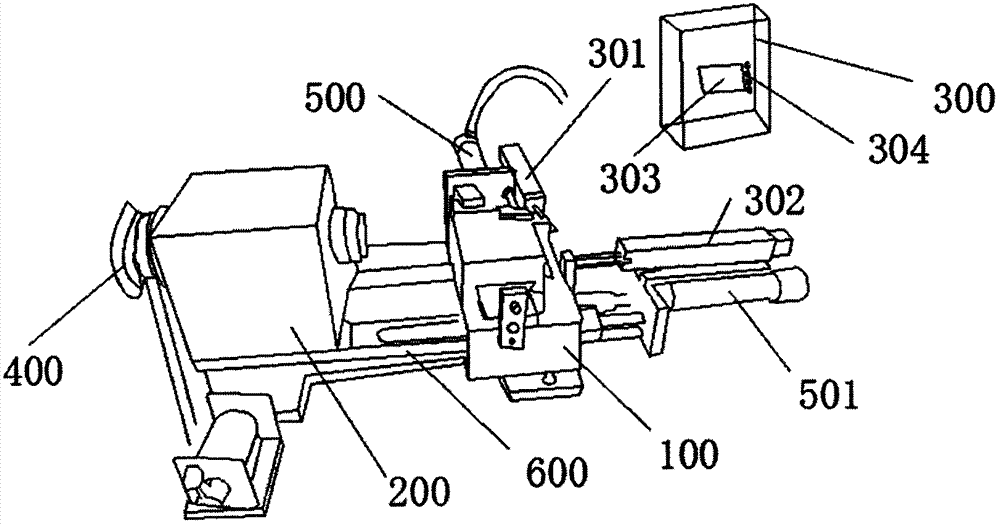
[0016] refer to figure 1 , an instrument lathe automation device, including a bed 600, a foot (not marked), a bed 200 and a work slide 100, the bed 200 is provided with a speed regulator 400, and the X-axis direction on the work slide 100 X-axis push cylinder 501 and Y-axis push cylinder 500 are respectively arranged in the X-axis direction and Y-axis direction, and a resistance scale 301, 302 is respectively arranged in the X-axis direction and Y-axis direction of the working slide table 100, and a control box 300 is also arranged on the foot. , The resistance scales 301, 302 are connected to the control box 300.

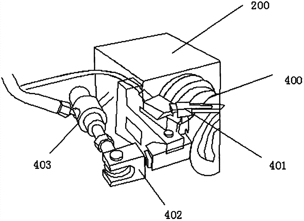
[0017] refer to figure 2 , a shifting cylinder 403 is...


PUM


Abstract

The invention relates to the field of instrument lathe automation, and discloses an instrument lathe automation device. By introducing a hydraulic power system into an ordinary instrument lathe, a set of brand-new control system is equipped to realize the automatic control of the instrument lathe and replace the traditional manual operation. This device replaces two hydraulic cylinders on the feed shaft of the original instrument lathe, and is equipped with two resistance scales at the same time to realize the coordinate feedback of the feed position. The control system realizes the position control of the machine tool by sampling the current coordinates, and introduces the resistance scale The advanced control system largely replaces the traditional PLC with the proximity switch as the position control method, which is an innovative way of automatic modification.

Description

technical field [0001] The invention belongs to the field of lathes, in particular to an automatic device for a lathe equipped with a resistance scale instrument. Background technique [0002] The current lathe automation equipment generally adopts PLC core control. The lathe of such a control system has no display screen, and the programming of product processing can only be fixed by the manufacturer when it is sold, which brings great limitations to processing. That is to say, one type of lathe can only process one type of product, and different products need to be replaced with different lathes, or the manufacturer can make a special program of lathes to complete the processing, which increases the cost of sales of its products . At the same time, the existing automatic instrument equipment basically uses PLC as the control core, and cooperates with the external proximity switch to realize the processing action. In this way, only point operations can be realized on the f...

Claims


Application Information

Patent Timeline
Patent Type & Authority Patents(China)
IPC IPC(8): G05B19/19
Inventor 徐亦志
Owner 徐亦志
Features
  • Generate Ideas
  • Intellectual Property
  • Life Sciences
  • Materials
  • Tech Scout
  • Unparalleled Data Quality
  • Higher Quality Content
  • 60% Fewer Hallucinations
Learn More