
A kind of cavitation self-rotating water buffer device

A buffer device and cavitator technology, which is applied in the direction of weapon types, self-propelled bombs, sea torpedoes, etc., can solve the problems of internal devices that are easy to overload and damage, and achieve a good jet effect

Active Publication Date: 2022-08-05
DALIAN UNIV OF TECH
View PDF6 Cites 0 Cited by
  • Summary
  • Abstract
  • Description
  • Claims
  • Application Information

AI Technical Summary

Problems solved by technology

[0003] The shortcomings of the flying body ejected from the air vehicle at high speed are also obvious. During the cross-medium flight, the flying body is subjected to considerable slamming force, and the internal devices are easily damaged by overload.

Method used


Image

  • A kind of cavitation self-rotating water buffer device
  • A kind of cavitation self-rotating water buffer device
  • A kind of cavitation self-rotating water buffer device

Examples


Embodiment Construction

[0043] It should be noted that the embodiments of the present invention and the features of the embodiments may be combined with each other under the condition of no conflict. The present invention will be described in detail below with reference to the accompanying drawings and in conjunction with the embodiments.

[0044]In order to make the purposes, technical solutions and advantages of the embodiments of the present invention clearer, the technical solutions in the embodiments of the present invention will be clearly and completely described below with reference to the accompanying drawings in the embodiments of the present invention. Obviously, the described embodiments It is only a part of the embodiments of the present invention, but not all of the embodiments. The following description of at least one exemplary embodiment is merely illustrative in nature and is in no way intended to limit the invention, its application, or uses. Based on the embodiments of the presen...


PUM


Abstract

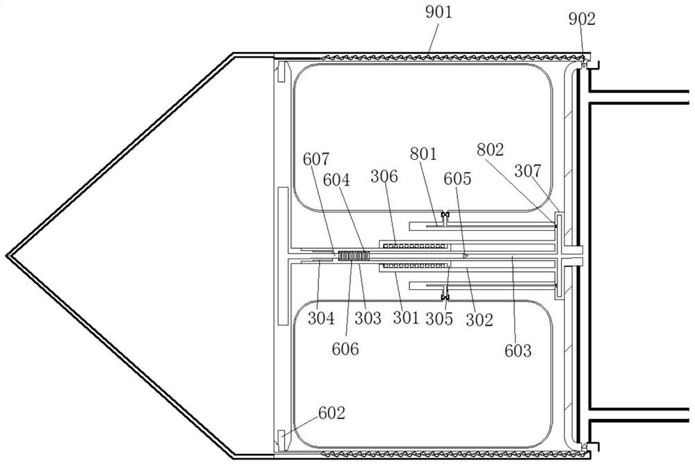
The invention provides a self-rotating water entry buffer device for a cavitation, comprising a head fairing, the rear end of the head fairing and the front end of the side fairing are detachably connected, and the rear end of the side fairing is connected to the front end of the side fairing. The head of the vehicle can be detachably connected, the side fairing is provided with a cavitation, the cavitation is connected to the vehicle through a buffer device, and the cavitation is rotatably connected to the output end of the buffer device , and the side fairing is provided with a rotary drive device that drives the cavitation to rotate around its axis. A plurality of buffer airbags are arranged around the buffer device in the side fairing, and a side wall jet system is arranged on the side wall of the side fairing. The present invention realizes the formation of larger supercavities by adopting the rotation of the cavitator. At the same time, the buffer air bag, sidewall jet system and buffer device are used to provide better buffer protection for the sailing body.

Description

technical field [0001] The invention relates to the technical field of water entry of a sailing body, in particular to a self-rotating water entry buffer device of a cavitation. Background technique [0002] The underwater vehicle that is launched underwater in the ordinary way is more likely to be detected by the enemy when performing tasks, and is easily restricted by complex environments or severe electromagnetic interference. Due to the advantages of strong mobility, more and more countries choose to develop air-launched underwater vehicles or aerial bombs instead of traditional underwater vehicles for launching. How to effectively implement the long-duration supercavitation navigation of the underwater vehicle is also a technical difficulty and focus, and how to form and maintain an effective supercavitation after entering the water has also become a severe test. [0003] The disadvantage of the high-speed shooting of the air vehicle by the air vehicle is also obvious....

Claims


Application Information

Patent Timeline
Patent Type & Authority Patents(China)
IPC IPC(8): F42B19/46
CPCF42B19/46
Inventor 李尧孙铁志宗智张润东
Owner DALIAN UNIV OF TECH
Learn More