
Fixed hanging rack and face recognition equipment

A hanger and equipment technology, applied in mechanical equipment, machine/stand, supporting machine, etc., can solve the problems of difficult disassembly, not easy to prevent theft, positioning fixtures or components that cannot be hidden, etc., so as to reduce the occupied space and facilitate removal. The effect of maintenance, reducing the risk of equipment theft

Pending Publication Date: 2022-01-28
GUANGDONG TELEPOWER TELECOM TECH
View PDF9 Cites 0 Cited by
  • Summary
  • Abstract
  • Description
  • Claims
  • Application Information

AI Technical Summary

Problems solved by technology

[0003] Face recognition equipment is usually equipped with positioning fixtures or components on the wall, and the face recognition equipment is fixed with the help of positioning fixtures or components such as screws, bolts and other fixtures. The positioning fixtures or components are generally placed on the surface of the wall , The positioning and fixing devices or components cannot be installed hidden in the wall, resulting in unsightly appearance. Moreover, only considering the fixing method of the face recognition device, the method of fixing the device with fixing parts is relatively simple, and it is not easy to prevent theft
In addition, if the fixing parts are installed from the front of the face recognition device, it will affect the appearance. If the fixing parts are installed from the back of the face recognition device, it is difficult to install and fix the face recognition device without specific positioning and fixing devices or specific tools. Moreover, when the equipment needs to be disassembled for maintenance, it is difficult to disassemble

Method used


Image

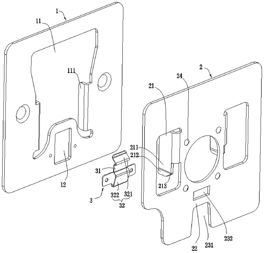
  • Fixed hanging rack and face recognition equipment
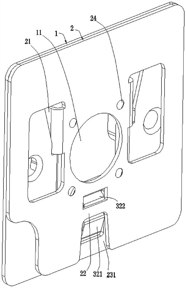
  • Fixed hanging rack and face recognition equipment
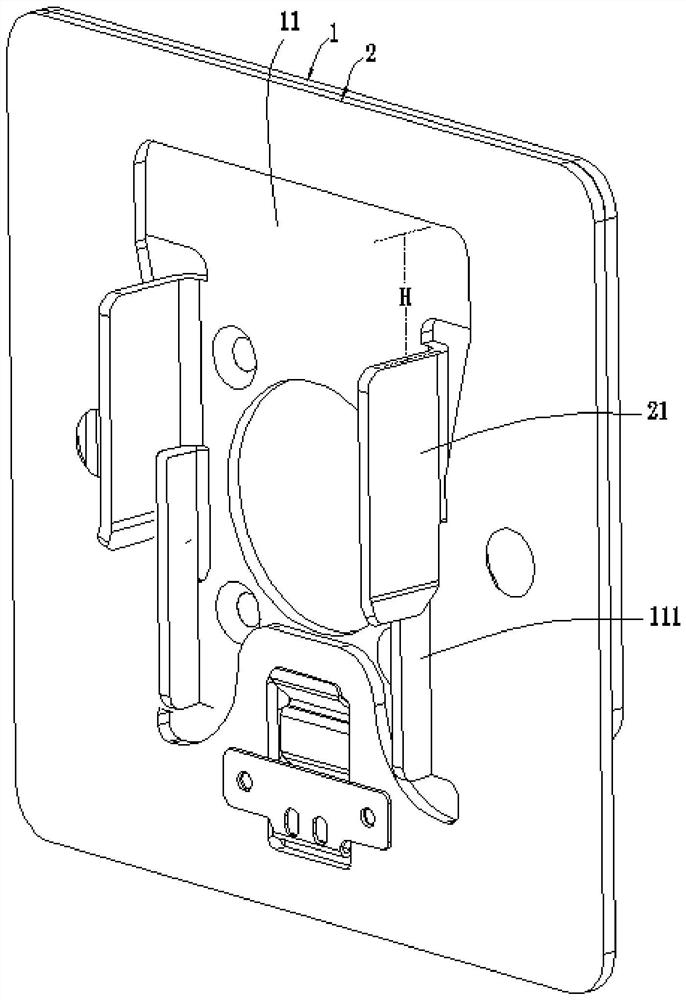
  • Fixed hanging rack and face recognition equipment

Examples


Embodiment Construction

[0033] In order to better illustrate the present invention, the present invention will be further described in detail below with reference to the accompanying drawings.

[0034] It should be clear that the described embodiments are only some of the embodiments of the present application, rather than all of the embodiments. Based on the embodiments in the embodiments of the present application, all other embodiments obtained by persons of ordinary skill in the art without making creative efforts belong to the protection scope of the embodiments of the present application.

[0035] The terms used in the embodiments of the present application are only for the purpose of describing specific embodiments, and are not intended to limit the embodiments of the present application. The singular forms "a", "said" and "the" used in the embodiments of this application and the appended claims are also intended to include plural forms unless the context clearly indicates otherwise. It shoul...


PUM


Abstract

The invention discloses a fixed hanging rack which comprises a first panel and a second panel which can be spliced; the first panel penetrates through a first cavity through a first clamping piece to be connected with the second panel in a clamped mode to conduct primary locking and tight attaching, and thus the occupied space after the first panel and the second panel are assembled is reduced; the first panel and the second panel can be integrally embedded into the wall body to be mounted without influencing fixation of wall-mounted equipment on the second panel, so that the first panel and the second panel are hidden in the wall body relative to the wall-mounted equipment, and the wall-mounted equipment is attractive after being mounted; a locking plate in a second cavity is matched with a locking strip on the second panel, the locking strip is arranged in a groove, the locking strip is clamped by two slope pieces, and the first panel and the second panel are secondarily locked, so that traditional screws and bolts are replaced for fixation, and the risk that equipment is stolen is reduced; and a special tool is inserted into a first unlocking cavity to separate the locking plate from the locking strip, so that the second panel is separated from the first panel, and the wall-mounted equipment is convenient to take down and maintain.

Description

technical field [0001] The invention relates to the technical field of vertical surface fixing of wall-mounted products, in particular to a fixing hanger and face recognition equipment. Background technique [0002] In existing products, such as face recognition devices, face recognition devices are generally fixedly installed on walls. [0003] Face recognition equipment is usually equipped with positioning fixtures or components on the wall, and the face recognition equipment is fixed with the help of positioning fixtures or components such as screws, bolts and other fixtures. The positioning fixtures or components are generally placed on the surface of the wall , The positioning and fixing devices or components cannot be hidden and installed in the wall, resulting in unsightly appearance. Moreover, only considering the fixing method of the face recognition device, the method of fixing the device with fixing parts is relatively simple, and it is not easy to prevent theft. ...

Claims


Application Information

Patent Timeline
Patent Type & Authority Applications(China)
IPC IPC(8): F16M11/04F16M13/02
CPCF16M11/04F16M13/02
Inventor 黄翔刘科泉
Owner GUANGDONG TELEPOWER TELECOM TECH
Learn More