Dimmable light guide plate and backlight module thereof

A light guide plate, dimming technology, applied in the direction of light guide, optics, optical components, etc., can solve the problem of insufficient energy concentration, and achieve the effect of improving the positive brightness

Active Publication Date: 2022-04-05
YANGXIN TECH SUZHOU +1
View PDF0 Cites 0 Cited by
  • Summary
  • Abstract
  • Description
  • Claims
  • Application Information

AI Technical Summary

Problems solved by technology

However, after the beam is delivered to the optimized geometric structure, a certain degree of stray light will still be formed, so that the energy of the beam is not concentrated enough after being refracted out of the light guide plate

Method used


Image

  • Dimmable light guide plate and backlight module thereof
  • Dimmable light guide plate and backlight module thereof
  • Dimmable light guide plate and backlight module thereof

Examples


Embodiment Construction

[0097] The foregoing and other technical contents, features and effects of the present invention will be clearly presented in the following detailed description of a preferred embodiment with reference to the accompanying drawings. The directional terms mentioned in the following embodiments, such as: up, down, left, right, front or back, etc., are only referring to the directions of the drawings. Accordingly, the directional terms are used to illustrate and not to limit the invention.

[0098] Reference will now be made in detail to the preferred embodiments of the present invention, examples of which are illustrated in the accompanying drawings. Wherever possible, the same reference numbers will be used in the drawings and description to refer to the same or like parts.

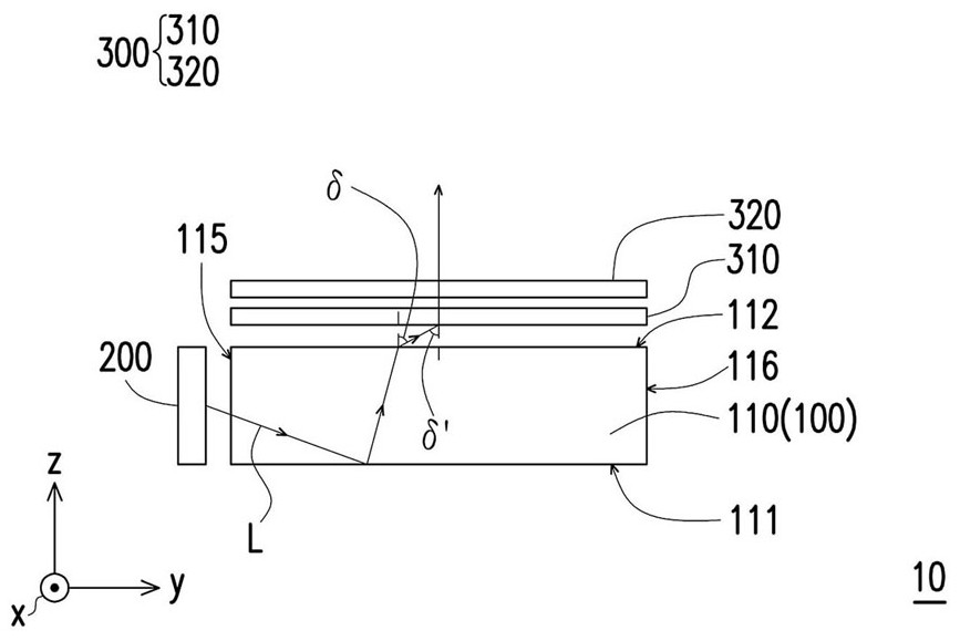
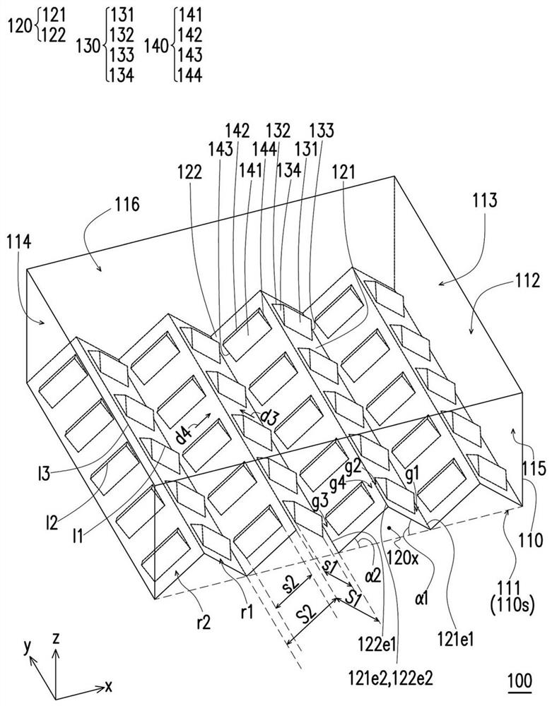
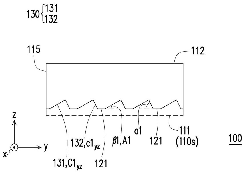
[0099] For the sake of clarity, most of the drawings in this specification draw a first direction y, a second direction x, and a direction z that are perpendicular to each other.

[0100] figure 1 It is ...


PUM


Abstract

The present invention provides a light-adjustable light guide plate, which includes a plate body, a plurality of strip structures, a plurality of first prism structures and a plurality of second prism structures. The plate body has a plurality of strip structures formed on the structure surface of the plate body. Each strip structure includes a first slope and a second slope which are respectively inclined to the structure surface and which are inclined in opposite directions. A plurality of first prism structures are disposed on the first slope. The plurality of second prism structures are disposed on the second slope and separated from the plurality of first prism structures. Each first prism structure and each second prism structure respectively have a light-receiving surface facing the light incident surface and a backlight surface facing away from the light incident surface. In addition, a backlight module including the above light-adjustable light guide plate has also been proposed. The light-adjustable light guide plate and its backlight module of the present invention can concentrate the energy of the light beam emitted therefrom, and can also finely control the outgoing angle of the light beam.

Description

technical field [0001] The present invention relates to a light guide plate and a backlight module, and in particular to a dimming type light guide plate and a backlight module. Background technique [0002] In the existing side-type backlight module, the light incident surface of the light guide plate receives the light beam from the light source. Destruction, and then the light beam is emitted from the upper surface of the light guide plate. Then, by means of the optical film group arranged on the light guide plate, the front luminance of the side-type backlight module is improved and the viewing angle range is controlled. [0003] In order to make the light inside the light guide plate more efficiently utilized by the optical film group, the geometric structure arranged on the upper surface or the lower surface of the light guide plate is usually optimized. However, after the light beam is transmitted to the optimized geometric structure, a certain degree of stray light...

Claims


Application Information

Patent Timeline
Patent Type & Authority Patents(China)
IPC IPC(8): G02B6/00
CPCG02B6/0036
Inventor 周民俊林宏泽李启龙林冠廷房昱赋杨越峰
Owner YANGXIN TECH SUZHOU
Why Eureka
Try Eureka