Optical imaging lens and imaging equipment

An optical imaging lens and lens technology, applied in optics, optical components, instruments, etc., can solve the problem of difficult correction of lens edge aberration, achieve good imaging effect, reduce the total length, and reduce the effect of axial chromatic aberration

Active Publication Date: 2019-11-12
JIANGXI LIANCHUANG ELECTRONICS CO LTD
View PDF3 Cites 0 Cited by
  • Summary
  • Abstract
  • Description
  • Claims
  • Application Information

AI Technical Summary

Problems solved by technology

[0003] High pixels mean smaller pixel size and larger imaging surface range. In this case, the resolution requirements of the lens are getting higher and higher, making it difficult to correct the edge aberration of the lens

Method used


Image

  • Optical imaging lens and imaging equipment
  • Optical imaging lens and imaging equipment
  • Optical imaging lens and imaging equipment

Examples


no. 1 example

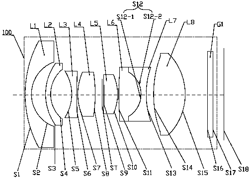
[0082] See figure 1 The optical imaging lens 100 provided by the first embodiment of the present invention is composed of eight lenses, from the object side to the imaging surface, including: a first lens L1, a second lens L2, a third lens L3, a fourth lens L4, Stop ST, fifth lens L5, sixth lens L6, seventh lens L7, eighth lens L8, and filter G1.

[0083] The first lens L1 has a negative refractive power, the object side surface S1 is a convex surface, the image side surface S2 is a concave surface, and the first lens L1 is a glass spherical lens.

[0084] The second lens L2 has a negative refractive power, the object side surface S3 is a convex surface, the image side surface S4 is a concave surface, and the second lens L2 is a glass aspheric lens.

[0085] The third lens L3 has a negative refractive power, the object side S5 and the image side S6 are both concave, and the third lens L3 is a glass spherical lens. In other embodiments of the present invention, the third lens L3 may ...

no. 2 example

[0100] For a schematic structural diagram of the optical imaging lens 200 of this embodiment, please refer to Figure 4 . The optical imaging lens 200 in this embodiment is substantially the same as the optical imaging lens 100 in the first embodiment, except that the image side surface S6 of the third lens L3 of the optical imaging lens 200 in this embodiment is convex, and The curvature radius and material selection of each lens are different.

[0101] The relevant parameters of each lens in the optical imaging lens 200 in this embodiment are shown in Table 3.

[0102] table 3

[0103]

[0104] The aspheric parameters of each lens in this embodiment are shown in Table 4.

[0105] Table 4

[0106]

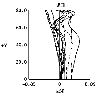
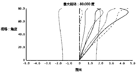
[0107] In this embodiment, its curvature of field and vertical axis chromatic aberration are as Figure 5 with Image 6 Shown. by Figure 5 with Image 6 It can be seen that the curvature of field and vertical axis chromatic aberration can be well corrected in this embodiment.

no. 3 example

[0109] For a schematic structural diagram of an optical imaging lens 300 provided in this embodiment, please refer to Figure 7 . The optical imaging lens 300 in this embodiment is substantially the same as the optical imaging lens 100 in the first embodiment. The difference is that the image side surface S6 of the third lens L3 of the optical imaging lens 300 in this embodiment is convex. The object side surface S7 of the four lens L4 is convex, and the curvature radius and material selection of each lens are different.

[0110] The relevant parameters of each lens in the optical imaging lens 300 in this embodiment are shown in Table 5.

[0111] table 5

[0112]

[0113] The aspheric parameters of each lens in this embodiment are shown in Table 6.

[0114] Table 6

[0115]

[0116] In this embodiment, its curvature of field and vertical axis chromatic aberration are as Figure 8 with Picture 9 Shown. by Figure 8 with Picture 9 It can be seen that the curvature of field and vertic...


PUM


Abstract

An optical imaging lens (100, 200, 300, 400, 500, 600, 700, 800) and an imaging device (900). The optical imaging lens (100, 200, 300, 400, 500, 600, 700, 800) consists of eight lenses, and sequentially comprises from an object side to an imaging surface (S18): a first lens (L1) having a negative focal power; a second lens (L2) having a negative focal power; a third lens (L3) having a negative focal power; a fourth lens (L4) having a positive focal power; a diaphragm (ST); a fifth lens (L5) having a positive focal power; a sixth lens (L6) having a positive focal power; a seventh lens (L7) having a negative focal power, wherein the sixth lens (L6) and the seventh lens (L7) form a bonding body; an eighth lens (L8) having a positive focal power; and an optical filter (G1) disposed between the eighth lens (L8) and the imaging surface (S18).

Description

Technical field [0001] The present invention relates to the field of lens imaging technology, in particular to an optical imaging lens and imaging equipment. Background technique [0002] In the field of outdoor extreme sports, such as skiing, surfing, skydiving, diving, racing, etc., there are severe vibrations and rapid changes in viewing angle. In this case, a small size and easy to carry, provide a larger field of view, and The imaging effect is good, and the distortion of the shot pictures is small. [0003] High pixels mean smaller pixel size and larger imaging area. In this case, the resolution requirements of the lens are getting higher and higher, making the edge aberration of the lens difficult to correct. [0004] Since the action camera is sensitive to the chip and converts the light signal into an electrical signal, and the short-wave sensitivity range of the chip is larger than that of the human eye, it needs better correction for the secondary chromatic aberration. S...

Claims


Application Information

Patent Timeline
Patent Type & Authority Patents(China)
IPC IPC(8): G02B13/00G02B13/18
CPCG02B13/0015G02B13/0045G02B13/006
Inventor 魏文哲陈伟建刘绪明曾吉勇
Owner JIANGXI LIANCHUANG ELECTRONICS CO LTD
Why Eureka
Try Eureka