
A solar charging device for a vehicle battery

A charging device and storage battery technology, which is applied in the direction of secondary batteries, battery pack components, and isolation of the battery from its environment. Vibration damage and other problems to achieve the effect of increasing the efficiency and convenience of use, preventing vibration damage, and ensuring safety

Active Publication Date: 2022-03-29
南通快猛电源有限公司
View PDF4 Cites 0 Cited by
  • Summary
  • Abstract
  • Description
  • Claims
  • Application Information

AI Technical Summary

Problems solved by technology

[0003] For example, the vehicle-mounted solar charging device whose publication number is CN107959320A, "it includes a first part, a second part flipped and movably connected to the first part, a solar photovoltaic panel arranged on the top side of the first part and the second part and arranged on the The wireless bracket module between the first part and the second part is used to support and wirelessly charge the vehicle-mounted device, and the two slider parts are both slidably installed in two opposite sides of the second slide rail", Although the vehicle-mounted solar charging device can combine solar charging and wireless charging, and has a bracket function that is easy to adjust, it cannot perform convenient and stable stretching installation and subsequent disassembly and folding work during the working process, so when the vehicle is driving When encountering bumps in the environment, it is very easy to cause vibration damage to the charging device, which cannot guarantee the safety of the charging device during use and the convenience of subsequent folding and storage work. At the same time, the charging device cannot be damaged during storage. Solar panels perform stable protection work, so it is necessary to provide a solar charging device for vehicle batteries to meet the needs of users

Method used


Image

  • A solar charging device for a vehicle battery
  • A solar charging device for a vehicle battery
  • A solar charging device for a vehicle battery

Examples


Embodiment

[0036] In order to make the purpose, technical solution and advantages of the present invention clearer, the following will further describe the implementation of the present invention in detail in conjunction with the accompanying drawings.

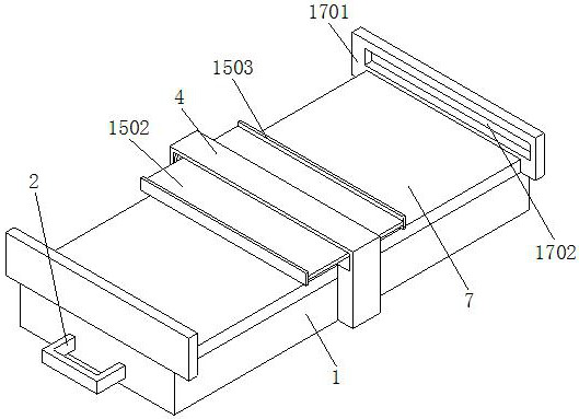
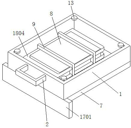
[0037] Such as Figure 1-10 As shown, a solar charging device for a vehicle battery includes a heat dissipation frame 1, a through hole 11 is opened on the heat dissipation frame 1, an electromagnetic control switch 12 is installed on the inner bolt of the heat dissipation frame 1, and an electromagnetic control switch 12 is installed on the inner bottom bolt of the heat dissipation frame 1. The suction cup 13 and the electromagnetic sucker 13 are covered with a rubber sleeve 14. The installation and disassembly of the whole device can be easily and stably completed by using the electromagnetic chuck 13. At the same time, the use of the rubber sleeve 14 can effectively prevent the electromagnetic chuck 13 from scratching the car, effectiv...


PUM


Abstract

The disclosure of the invention belongs to the field of automobile charging, and is specifically a solar charging device for a vehicle battery, including a heat dissipation frame, an electromagnetic control switch is installed on a bolt inside the heat dissipation frame, and an electromagnetic chuck is installed on an inner bottom bolt of the heat dissipation frame. The electromagnetic chuck is covered with a rubber sleeve, a cooling component is installed in the heat dissipation frame, a protective component is installed on the top of the connecting plate, and the top of the connecting plate is internally screwed to a limit frame, and the limit The scroll spring is welded and fixed in the frame, and the top surface of the heat dissipation frame is equipped with a fastening and fixing component, which solves the problem that the existing charging device cannot be easily and stably extended and installed and subsequently disassembled and folded during the working process. When the vehicle encounters bumps during driving, it is very easy to cause vibration damage to the charging device, which cannot guarantee the safety of the charging device during use and the convenience of subsequent folding and storage work.

Description

technical field [0001] The invention relates to the field of car charging, in particular to a solar charging device for a car battery. Background technique [0002] Since the car needs to use the power supply in the battery to start the car when it is starting, the battery must have sufficient power to ensure that the car can start normally. Electric energy is used to supplement electricity, and with the development of science and technology, people are increasingly using solar energy as a new energy source. Therefore, when people drive vehicles, they can use solar charging devices for photoelectric conversion and store electrical energy in batteries. , for the convenience of the people in the car, or to provide power for the car, but there are some problems in the use of the conventional solar charging device for the battery of the car; [0003] For example, the vehicle-mounted solar charging device whose publication number is CN107959320A, "it includes a first part, a sec...

Claims


Application Information

Patent Timeline
Patent Type & Authority Patents(China)
IPC IPC(8): H02S10/40H02S20/00H02S40/00H02S40/38H02S40/42H01M10/613H01M10/625H01M10/6551H01M10/6556H01M10/6563H01M10/6568H01M50/204H01M50/24H01M50/244H01M50/249H01M50/264
CPCH02S40/38H02S40/42H02S20/00H02S10/40H02S40/00H02S40/425H01M10/613H01M10/625H01M10/6556H01M10/6563H01M10/6568H01M50/264H01M50/244H01M50/204H01M50/249H01M10/6551H01M50/24Y02E10/50Y02E60/10Y02E70/30
Inventor 杨海涛沈维新沈煜婷
Owner 南通快猛电源有限公司
Learn More