System for managing PCIE equipment based on Openstack platform
A platform management and equipment technology, applied in the computer field, can solve the problem that various heterogeneous PCIE devices cannot achieve unified scheduling, and achieve the effect of unified scheduling management
Pending Publication Date: 2022-02-25
INST OF AUTOMATION CHINESE ACAD OF SCI +1
0 Cites 0 Cited by
AI-Extracted Technical Summary
Problems solved by technology
[0005] In order to solve the above problems in the prior art, that is, in order to solve the problem that the management of various heterogeneous PCIE devices in the heterogeneous computing platform cannot realize unified scheduling, t...
Abstract
The invention belongs to the technical field of computers, and particularly provides a system for managing PCIE (Peripheral Component Interface Express) equipment based on an Openstack platform, which comprises a management node and one or more calculation nodes, the management node and the calculation node are connected through a communication link; the management node comprises an equipment information base and a first management module; the equipment information base comprises a Baiming list equipment list and a corresponding PCIE equipment state; the calculation node comprises one or more PCIE (Peripheral Component Interface Express) equipment and a second management module; the first management module is configured to create a KVM virtual machine based on the PCIE equipment in the equipment information base; before the virtual machine is created, the second management module virtualizes the PCIE device selected and configured by the first management module and transmits the virtualized PCIE device to the kvm virtual machine. According to the invention, unified scheduling of various heterogeneous devices in the heterogeneous calculation platform can be realized.
Application Domain
Software simulation/interpretation/emulation
Technology Topic
VirtualizationTelecommunications link +7
Image
Examples
- Experimental program(1)
Example Embodiment
[0027] In order to make the objectives, technical solutions and advantages of the present invention clearer, the technical solutions in the embodiments of the present invention will be clearly and completely described below with reference to the accompanying drawings. Obviously, the described embodiments are part of the embodiments of the present invention, not All examples. Based on the embodiments of the present invention, all other embodiments obtained by those of ordinary skill in the art without creative efforts shall fall within the protection scope of the present invention.
[0028] The present application will be further described in detail below with reference to the accompanying drawings and embodiments. It should be understood that the specific embodiments described herein are only used to explain the related invention, but not to limit the invention. In addition, it should be noted that, for the convenience of description, only the parts related to the related invention are shown in the drawings.
[0029] It should be noted that the embodiments in the present application and the features of the embodiments may be combined with each other in the case of no conflict.
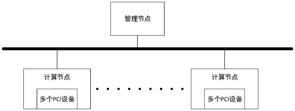
[0030] A system for managing PCIE devices based on the Openstack platform of the present invention, such as figure 1 shown includes a management node, one or more computing nodes; the management node and the computing node are connected by a communication link;
[0031] The management node includes a device information base and a first management module; the device information base includes a clear single device list and a corresponding PCIE device state;
[0032] The computing node includes one or more PCIE devices and a second management module;
[0033] The first management module is configured to create a KVM virtual machine based on the PCIE device in the device information base; before creating the virtual machine, the second management module virtualizes the PCIE device selected by the first management module and transparently transmitted to the kvm virtual machine.
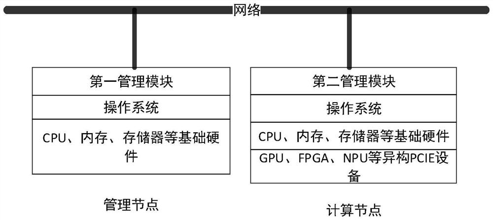
[0034] In order to more clearly describe the system of the present invention for managing PCIE devices based on the Openstack platform, the following is combined with the appendix. figure 2 An embodiment of the present invention will be described in detail.
[0035] A system for managing PCIE devices based on an Openstack platform according to an embodiment of the present invention includes a management node and one or more computing nodes; the management node and the computing node are connected through a communication link. The management node and the computing node respectively have their own operating systems. The management node includes a device information base, a first management module, and also includes a human-computer interaction module; the computing node includes one or more PCIE devices and a second management module.
[0036] In this embodiment, the management node may be a computer system, the human-computer interaction module is a web service system, and the input content and display content of the human-computer interaction may be operated and displayed through a web page. High-performance memory, CPU, storage, and PCIE device resources are installed on the computing node, and computing services are running.
[0037] The device information base includes a list of clear single devices and the corresponding PCIE device status; a human-computer interaction module is used to input information and display information according to the input instructions; the first management module is configured to create a KVM based on the PCIE devices in the device information base. For a virtual machine, before the virtual machine is created, the second management module virtualizes the PCIE device selected by the first management module, and transparently transmits it to the kvm virtual machine.
[0038] This embodiment adopts a whitelist strategy, and the user can add a whitelist on the operation interface of the human-computer interaction module. The whitelist includes: device ID, manufacturer ID, and device alias (the device alias is an alias defined by the user for the device). After the user confirms, the management node issues the whitelist to all computing nodes. By running the computing service, the computing node periodically reads the PCIE devices on the server through libvirt, filters the PCIE devices according to the whitelist, and writes the location information, ID information, and usage status of the devices into the device information database of the management node.
[0039]The process of adding the whitelist is described in detail as follows:
[0040] (1) The user adds the PCIE device to be added to the whitelist on the web page. The data structure of the whitelist includes the vendor ID (vendor ID) of the PCIE device, the device product ID (device ID), and the alias label defined by the user for the device.
[0041] (2) After the user adds the whitelist, the management node sends a message through RabbitMQ to update the whitelist to all computing nodes. RabbitMQ is an open source message broker software (also known as message-oriented middleware) that implements the Advanced Message Queuing Protocol (AMQP).
[0042] (3) All computing nodes periodically count PCIE device information, including device slot location, vendor ID, device product ID, label (custom label), and the NUMA node of the associated CPU, and update it to the management node device in the information base. label refers to the device alias customized by the user for the device. numa_node is a parameter related to the cpu slot. In order to achieve the best performance of the device, the PCIE device should be in the same NUMA NODE as the CPU core and memory.
[0043] The management node displays the PCIE devices in the device information library on the operation interface of the human-computer interaction module, and classifies the PCIE devices according to the device ID information. For example, the PCIE devices can be divided into GPU, FPGA, NPU, network card, etc. Type, as well as the compute node where it is located, the slot location, and the status of whether it is occupied. The user can see all the device information on the whitelist on the operation interface of the human-computer interaction module. When sorting, you can look up device suppliers by supplier ID, product names by device product ID, and then sort based on device suppliers and/or product names.
[0044] In this embodiment, the device information database obtains the device name and the device manufacturer based on the device ID and the manufacturer ID of the PCIE device, respectively, and performs classification management according to a preset classification rule. The preset classification rules include classification based on device names, classification based on device manufacturers, or comprehensive classification based on device names and device manufacturers. For example, it can be divided into multiple types such as GPU, FPGA, NPU, network card, etc., and can also be classified into A, B, and C manufacturers, and can also classify different types of network cards from each manufacturer.
[0045] Based on the above system for managing PCIE devices based on the Openstack platform, the process of creating a virtual machine is as follows:
[0046] Step S100, through the first management module, select an additional PCIE device from the device information library.
[0047] In this embodiment, the user selects an additional PCIE device for generating a virtual machine through the web page of the human-computer interaction module of the management node.
[0048] The management node searches for the computing nodes that meet the requirements on all computing nodes through the NOVA component of Openstack. Specifically, after the creation starts, manage the PCIE device statistics and cpu, memory, storage and other information in the root device information base of the node, and select a suitable computing node according to the scheduling policy to generate a virtual machine instance.
[0049] Step S200, through the second management module, perform transparent transmission virtualization on the selected additional PCIE device.
[0050] In the selected computing node in step S100, the second management module performs transparent transmission virtualization on the selected additional PCIE device, and after the device loads the vfio-pci driver correctly, the virtualization is completed.
[0051] The purpose of virtualizing PCIE devices is to put PCIE devices on virtual machines and provide users with heterogeneous computing cloud services such as GPU cloud, FPGA cloud, and NPU cloud. Passthrough (pci passthrough) is a way of virtualization, which separates the device from the physical server and directly assigns it to the virtual machine in an exclusive form. The advantage of transparent transmission is that the PCIE device has high working efficiency in the virtual machine environment, which is close to the bare metal environment, and is suitable for high-performance heterogeneous computing scenarios.
[0052] Step S300, generate a kvm virtual machine through libvirt (libvirt is an existing virtual machine management tool) api scheduling and mount a corresponding PCIE device.
[0053] After the virtual machine is created, it also includes the following steps:
[0054] After the virtual machine is created, the PCIE device state added by creating the virtual machine in the device information base is updated to the used state;
[0055] When deleting a virtual machine, the management node updates the state of the released PCIE device to an unused state while deleting the virtual machine through libvirt scheduling.
[0056] In this embodiment, the computer node regularly uploads the statistical PCIE device information according to the whitelist provided by the user, and the computing node will find a qualified computing node according to the request of the control node, create the required virtual machine instance, and Before creating a virtual machine, virtualize the selected PCIE device, and transparently transmit the device to the kvm virtual machine to realize unified management of PCIE devices, without requiring differentiated management and system software configuration for different types of PCIE devices. A method is proposed to construct heterogeneous computing clusters and provide heterogeneous computing cloud services.
[0057] In order to further illustrate the technical solution of the present invention, a specific example is used for further explanation below.
[0058] The prerequisites for virtualization are:
[0059] Enable hardware-assisted virtualization in the BIOS and install the Linux operating system.
[0060] Start the IOMMU (i/o memory management unit) module in the kernel.
[0061] If you are using an Intel CPU, add in /etc/default/grub: GRUB_CMDLINE_LINUX_DEFAULT="intel_iommu=on"
[0062] If you are using AMD CPU, modify GRUB_CMDLINE_LINUX_DEFAULT="amd_iommu=on iommu=pt kvm_amd.npt=1kvm_amd.avic=1" in /etc/default/grub
[0063] Regenerate the GRUB boot menu configuration file with the sudo update-grub command, update and restart the server.
[0064] The specific steps of virtualization include:
[0065] Detach the PCIE device from the physical server and load the pcie virtualization driver VFIO-PCI. For virtual machines based on kvm virtualization, use the virsh detach command in the virsh tool.
[0066] The GPU device and other devices in the PCIE device often come with additional interfaces such as audio device (audio device) and usb, and the PCIE device itself belongs to the same IOMMU group by default. When using transparent transmission, a single device in the same IOMMU group cannot be transparently transmitted to the KVM virtual machine, otherwise the transparent transmission will fail. Therefore, multiple devices in one IOMMU group are separated into different IOMMU groups.
[0067] Suppose the device's ID is 10de:1e07 The physical location is: 05:00.0
[0068] Load the VFIO-PCI driver to the specified PCIE device: sudo sh-c'echo"10de 1e07">/sys/bus/pci/drivers/vfio-pci/new_id’
[0069] And unbind the device from the physical machine: virsh nodedev-detach pci_0000_05_00_0
[0070] After the virtualization is successful, run lspci-nnv on the Linux system to check whether the vfio-pci driver is loaded normally. If the displayed information includes: Kernel driver in use:vfio-pci, the driver is loaded normally.
[0071] After confirming that the driver status is vifio-pci and the IOMMU where the device is located is grouped into a device, openstack creates a KVM virtual machine through libvirt api calls, and attaches (mounts) the selected PCIE device.
[0072] After the creation is complete, the device information library will change the PCIE device usage status to used.
[0073] In particular, according to embodiments of the present disclosure, the processes described above with reference to the flowcharts may be implemented as computer software programs. For example, embodiments of the present disclosure include a computer program product comprising a computer program carried on a computer-readable medium, the computer program containing program code for performing the method illustrated in the flowchart. In such an embodiment, the computer program may be downloaded and installed from a network via the communication portion, and/or installed from a removable medium. When the computer program is executed by a central processing unit (CPU), the above-mentioned functions defined in the method of the present application are performed. It should be noted that the computer-readable medium mentioned above in the present application may be a computer-readable signal medium or a computer-readable storage medium, or any combination of the above two. The computer-readable storage medium can be, for example, but not limited to, an electrical, magnetic, optical, electromagnetic, infrared, or semiconductor system, apparatus or device, or a combination of any of the above. More specific examples of computer readable storage media may include, but are not limited to, electrical connections with one or more wires, portable computer disks, hard disks, random access memory (RAM), read only memory (ROM), erasable Programmable read only memory (EPROM or flash memory), fiber optics, portable compact disk read only memory (CD-ROM), optical storage devices, magnetic storage devices, or any suitable combination of the foregoing. In this application, a computer-readable storage medium can be any tangible medium that contains or stores a program that can be used by or in conjunction with an instruction execution system, apparatus, or device. In this application, however, a computer-readable signal medium may include a data signal propagated in baseband or as part of a carrier wave, carrying computer-readable program code therein. Such propagated data signals may take a variety of forms, including but not limited to electromagnetic signals, optical signals, or any suitable combination of the foregoing. A computer-readable signal medium can also be any computer-readable medium other than a computer-readable storage medium that can transmit, propagate, or transport the program for use by or in connection with the instruction execution system, apparatus, or device . Program code embodied on a computer readable medium may be transmitted using any suitable medium including, but not limited to, wireless, wireline, optical fiber cable, RF, etc., or any suitable combination of the foregoing.
[0074]Computer program code for performing the operations of the present application may be written in one or more programming languages, including object-oriented programming languages—such as Java, Smalltalk, C++, but also conventional Procedural programming language - such as the "C" language or similar programming language. The program code may execute entirely on the user's computer, partly on the user's computer, as a stand-alone software package, partly on the user's computer and partly on a remote computer, or entirely on the remote computer or server. In the case of a remote computer, the remote computer may be connected to the user's computer through any kind of network, including a local area network (LAN) or a wide area network (WAN), or may be connected to an external computer (eg, using an Internet service provider through Internet connection).
[0075] The flowchart and block diagrams in the Figures illustrate the architecture, functionality, and operation of possible implementations of systems, methods and computer program products according to various embodiments of the present application. In this regard, each block in the flowchart or block diagrams may represent a module, segment, or portion of code that contains one or more logical functions for implementing the specified functions executable instructions. It should also be noted that, in some alternative implementations, the functions noted in the blocks may occur out of the order noted in the figures. For example, two blocks shown in succession may, in fact, be executed substantially concurrently, or the blocks may sometimes be executed in the reverse order, depending upon the functionality involved. It is also noted that each block of the block diagrams and/or flowchart illustrations, and combinations of blocks in the block diagrams and/or flowchart illustrations, can be implemented in dedicated hardware-based systems that perform the specified functions or operations , or can be implemented in a combination of dedicated hardware and computer instructions.
[0076] The terms "first," "second," etc. are used to distinguish between similar objects, and are not used to describe or indicate a particular order or sequence.
[0077] The term "comprising" or any other similar term is intended to encompass a non-exclusive inclusion such that a process, method, article or device/means comprising a list of elements includes not only those elements but also other elements not expressly listed, or Also included are elements inherent to these processes, methods, articles or devices/devices.
[0078] So far, the technical solutions of the present invention have been described with reference to the preferred embodiments shown in the accompanying drawings, however, those skilled in the art can easily understand that the protection scope of the present invention is obviously not limited to these specific embodiments. Without departing from the principle of the present invention, those skilled in the art can make equivalent changes or substitutions to the relevant technical features, and the technical solutions after these changes or substitutions will fall within the protection scope of the present invention.
PUM


Description & Claims & Application Information
We can also present the details of the Description, Claims and Application information to help users get a comprehensive understanding of the technical details of the patent, such as background art, summary of invention, brief description of drawings, description of embodiments, and other original content. On the other hand, users can also determine the specific scope of protection of the technology through the list of claims; as well as understand the changes in the life cycle of the technology with the presentation of the patent timeline. Login to view more.