Rapid positioning and tracking method and device for assisting robot

A positioning tracking and robot technology, applied in the field of robot navigation, positioning and tracking, can solve the problems of complicated optional devices, poor positioning accuracy, and large amount of calculation, and achieve the effect of simplifying surgical steps, saving operation time, and reducing the amount of calculation.

Active Publication Date: 2022-03-01
ZHUHAI WEIERKANG BIOTECH
View PDF10 Cites 3 Cited by
  • Summary
  • Abstract
  • Description
  • Claims
  • Application Information

AI Technical Summary

Problems solved by technology

The displacement of any coordinate point in different coordinate systems will lead to a recalculation process. Due to the large amount of calculation and the limitation of computer computing power, the data acquisition of the robot is delayed. Timely dynamic tracking, which leads to prolonged registration time or even failure of registration of such robots in surgery
For example, the patent No. CN112932667A discloses a surgical navigation system, which adopts the optical navigation technology commonly used in the existing robot technology. There is an optical positioning board that needs to be fixed by Kirschner wires, and there may be deviations in positioning after rotation ( The positioning board is fixed at a single point and the optional device is complicated. The comparison patent also introduces the third coordinate system of optical navigation for tracking and positioning, which also cannot achieve fast tracking and other problems. At the same time, the positioning of the special positioning ruler on the human body is also cumbersome and the positioning accuracy is poor.

Method used


Image

  • Rapid positioning and tracking method and device for assisting robot
  • Rapid positioning and tracking method and device for assisting robot
  • Rapid positioning and tracking method and device for assisting robot

Examples


Embodiment Construction

[0028] The following will clearly and completely describe the technical solutions in the embodiments of the present invention with reference to the accompanying drawings in the embodiments of the present invention. Obviously, the described embodiments are only some, not all, embodiments of the present invention. Based on the embodiments of the present invention, all other embodiments obtained by persons of ordinary skill in the art without making creative efforts belong to the protection scope of the present invention.

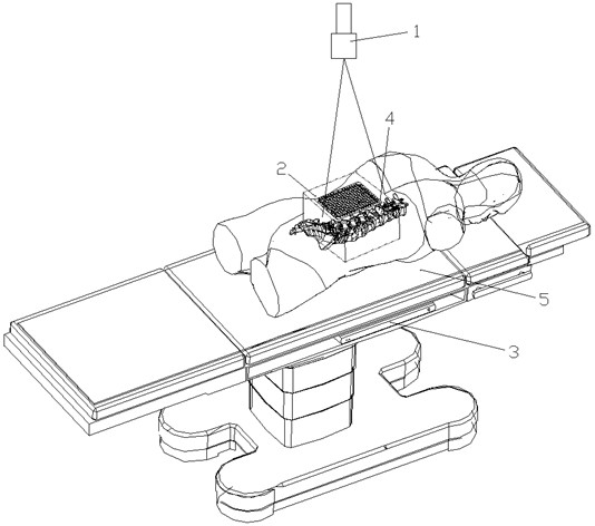
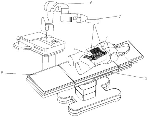
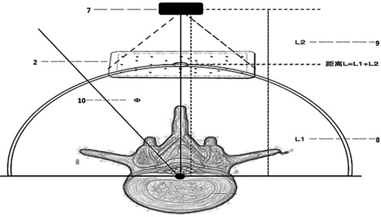
[0029] The invention relates to the technical field of auxiliary robot navigation, positioning and tracking, and is a technology that adopts MRI image measurement before use, static fusion of X-ray images during use, and three-dimensional visual imaging measurement at the working end of the robot, laser-assisted positioning, and visual tracking and positioning technologies to realize the robot. In the operation, there is no need to rely on special navigation eq...


PUM


Abstract

The invention discloses a rapid positioning and tracking method for an auxiliary robot. The method comprises the following steps: S1, determining a position relation between a target size and a bony mark point through an MRI image; s2, establishing a first coordinate system between the body surface positioning plate and the target spot and a second coordinate system between the body surface positioning plate and an auxiliary robot visual positioning device, correcting the two coordinate systems into a standard coordinate system through calculation by taking the body surface positioning plate as a standard, and controlling the auxiliary robot to position according to the standard coordinate system; s3, through MRI image measurement, image fusion measurement and calculation are carried out in combination with X-ray pictures shot in real time in the operation process, real-time data of the target spot on the body surface positioning plate are obtained, a visual positioning device of the auxiliary robot carries out precise puncture positioning and tracking of movement of the target spot according to the position data of the target spot on the body surface positioning plate, and the target spot is accurately positioned. Meanwhile, the corresponding device is disclosed, the overall principle is simple, the robot system cost is reduced, efficient operation of the robot is achieved, and the operation difficulty is reduced.

Description

technical field [0001] The invention relates to the technical field of robot navigation, positioning and tracking, in particular to a fast positioning and tracking method for an auxiliary robot, and also to a fast positioning and tracking device for an auxiliary robot. Background technique [0002] During the use of auxiliary robots, precise puncture and positioning of targets, and fast tracking of target movement are the main points of medical robot applications. Existing positioning technology mainly adopts pre-use planning. During use, the image and navigation device control the positioning and movement of the robot. The precise positioning and tracking of the target needs to establish a unified coordinate system from the three independent coordinate systems of image, navigation and robot. This process is carried out through the computer. Realization of dynamic calculation. The displacement of any coordinate point in different coordinate systems will lead to a recalculat...

Claims


Application Information

Patent Timeline
Patent Type & Authority Applications(China)
IPC IPC(8): A61B34/20A61B34/30A61B90/13
CPCA61B34/20A61B2034/2065
Inventor 胡善云梁泳强丘永洪肖伟鹏李小雪
Owner ZHUHAI WEIERKANG BIOTECH
Why Eureka
Try Eureka