
Focus locking detection system and method of microscope

A detection system and detection method technology, which is applied in the field of microscope focus detection system, can solve problems such as limited size, impossible detection, complex system, etc., and achieve the effect of precise detection

Pending Publication Date: 2022-03-01
广东粤港澳大湾区黄埔材料研究院
View PDF5 Cites 0 Cited by
  • Summary
  • Abstract
  • Description
  • Claims
  • Application Information

AI Technical Summary

Problems solved by technology

[0003] 1. The existing solution uses the lateral magnification of the microscope. The existing microscope itself has a magnification of 100x, and then increases the magnification by about 2 times through the optical path. The total magnification is about 200x, and it is impossible to achieve more precise detection
[0004] 2. In the focus lock detector module, due to the limited size, it is impossible to achieve a larger magnification. In order to increase the magnification, a more complex system is required.

Method used


Image

  • Focus locking detection system and method of microscope
  • Focus locking detection system and method of microscope
  • Focus locking detection system and method of microscope

Examples


Embodiment 1

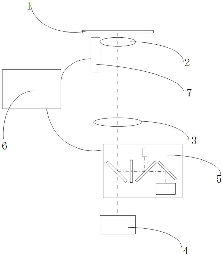
[0050] see Figure 1-3 1. A focus-locking detection system of a microscope, comprising: an objective lens 2, a tube lens 3, a focus-locking detection module 5, a focus-locking controller 6, a Z-axis displacement device 7, and an imaging CCD4; the Z-axis displacement device 7 is arranged on the objective lens 2 The side of the sample; the objective lens 2 is directly below the sample 1, the tube lens 3 is directly below the objective lens 2, the imaging CCD4 is directly below the tube lens 3, and the focus detection module 5 is between the tube lens 3 and the imaging CCD4, The focus detection module 5, the focus controller 6, and the Z-axis shifter 7 are connected in sequence.

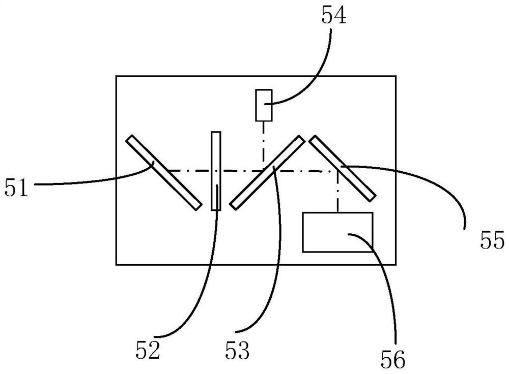
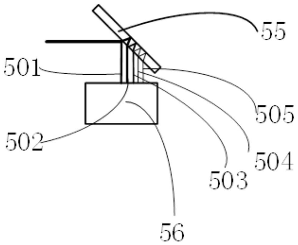
[0051] In this embodiment, the focus detection module 5 includes: a first spectroscopic lens 51, a quarter wave plate 52, a second spectroscopic lens 53, a light source 54, a third spectroscopic lens 55 and a linear detector 56; The mirror 51 is obliquely arranged directly below the tube mirror 3, the ...

Embodiment 2

[0101] see Figure 4 The difference between Embodiment 2 and Embodiment 1 is that the focus detection module 5 further includes: a collimating lens 57; The straight lens 57, the first dichroic mirror 51 and the quarter wave plate 52 are on the same horizontal optical axis. The focus lock detection method also includes: the circularly polarized light passing through the quarter-wave plate enters the collimating lens 57, becomes parallel light after passing through the collimating lens 57, and the parallel light enters the first spectroscopic lens 51; the light reflected by the sample 1 After being reflected by the dichroic mirror, it enters the collimating lens 57 , becomes focused light after passing through the collimating lens 57 , and the focused light enters the first dichroic mirror 51 . Embodiment 2 avoids the loss of light used for imaging by adding a collimating lens 57 .

[0102] In the present invention, the axial magnification is used as the optical magnification ...


PUM


Abstract

The invention discloses a focus-locking detection system and method for a microscope, and the method comprises the steps: a focus-locking detection module detects the variable quantity of the distance between an objective lens and a sample, and transmits the variable quantity of the distance to a focus-locking controller, the focus-locking controller outputs a movement distance to a Z-axis shifter, the Z-axis shifter moves the distance to drive the objective lens 1 to move, and the objective lens 1 is driven to move. And keeping the distance between the objective lens and the sample within a preset focal length value. According to the invention, the lateral magnification is not used as the magnification of the optical size, the axial magnification is used as the optical magnification, the axial magnification is measured, and the axial magnification is in direct proportion to the square of the lateral magnification, so that more precise detection is realized.

Description

technical field [0001] The invention relates to the technical field of microscope ranging, in particular to a microscope focus-locking detection system and method. Background technique [0002] Focus locking is to lock the distance between the objective lens of the microscope and the sample, that is, the focal plane of the objective lens. The focus locking system consists of two parts: one is the detector, which is used to detect the distance between the sample and the objective lens in real time; the other is the precision shifter. Because the general objective lens and sample displacement are between 20nm and 50nm, a precise detector is required that can detect values ​​of 20nm or less. Therefore, the most important technical point of the lock-in detector is to amplify the 20nm to the extent that it can be detected. The existing detector system has the following disadvantages: [0003] 1. The existing solution uses the lateral magnification of the microscope. The existi...

Claims


Application Information

Patent Timeline
Patent Type & Authority Applications(China)
IPC IPC(8): G02B21/24G02B27/10G02B27/28G02B21/36G02B21/06
CPCG02B21/241G02B27/10G02B27/286G02B27/283G02B21/36G02B21/06
Inventor 杨乐宝王宏达
Owner 广东粤港澳大湾区黄埔材料研究院
Learn More