Convertible catheter sheath

A catheter and blood vessel technology, applied in the field of catheter sheath, can solve the problem of not allowing users to place intravascular devices, etc.

Pending Publication Date: 2022-03-29
타우카디오인크
View PDF8 Cites 0 Cited by
  • Summary
  • Abstract
  • Description
  • Claims
  • Application Information

AI Technical Summary

Problems solved by technology

However, existing introducer sheaths do not allow users to place larger intravascular devices during the procedure

Method used


Image

  • Convertible catheter sheath
  • Convertible catheter sheath
  • Convertible catheter sheath

Examples


Embodiment Construction

[0031] In the drawings, the same reference numerals may denote the same parts. Certain terms are used for convenience of description, but should not be construed as limiting the invention. The terms "distal" and "proximal" refer to directions "away from" and "closer to", respectively, the body of a physician who is inserting an introducer sheath into a patient. Terms include the explicitly mentioned meanings, their derived meanings and similar extended meanings.

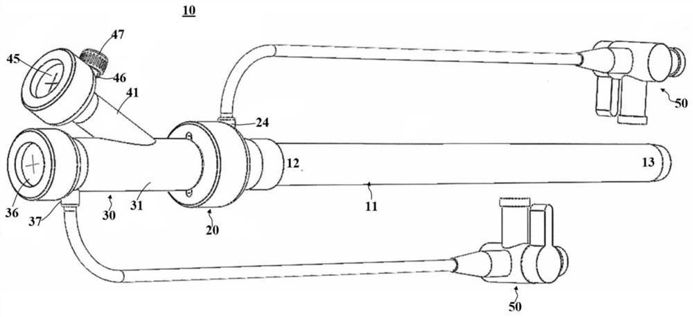
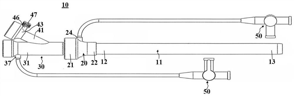
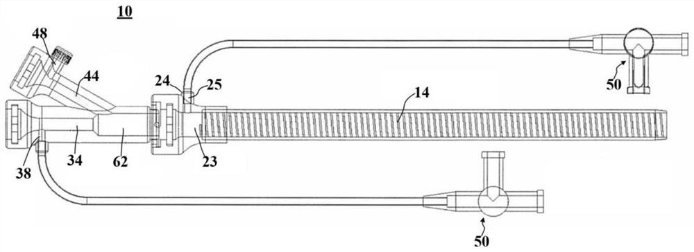
[0032] figure 1 , figure 2 and Figure 4 Schematic perspective and side views of an introducer sheath according to the present disclosure are shown. In this embodiment, the introducer sheath 10 may include a tubular member 11, a first hub 20 (hub), and a second hub 30 (hub). The first sleeve 20 may include a side hole 24 connected to a three-way stopcock 50 . The long arm portion 31 of the second sleeve 30 includes a side hole 37 connected to another three-way cock 50 . The short arm portion 41 of the second ...


PUM


Abstract

A vascular catheter sheath device of the present disclosure includes a tubular spindle and a main sleeve attached to a proximal end of the tubular spindle. The head sleeve is attached to the proximal end of the main sleeve, having a first arm and a second arm. The head sleeve is attached to the main sleeve in a releasable locking configuration. Therefore, the head sleeve is functionally detachably connected with the main sleeve. The head sleeve and the main sleeve may collectively have a twisted or snapped mating mechanism, such as a male lock on the head sleeve and a female lock on the main sleeve. Furthermore, a side hole is provided in the main sleeve and a side hole is provided in the head sleeve, the side hole of the main sleeve and the side hole of the head sleeve being oriented in the same plane when the head sleeve and the main sleeve are in the locked configuration.

Description

technical field [0001] The present disclosure generally relates to introducer sheaths for access into and out of blood vessels. Background technique [0002] Various introducer sheaths for accessing and exiting blood vessels already exist. However, existing introducer sheaths do not allow users to place larger intravascular devices during the procedure. Accordingly, it would be desirable to provide a vascular access introducer sheath that can have a releasable proximal sleeve so that the introducer sheath does not need to be replaced during a procedure for direct access of larger intravascular devices. Contents of the invention [0003] According to one aspect, the present disclosure provides a vascular introducer sheath device comprising a tubular main shaft (11) having a shaft channel (14). A main sleeve (20) is attached to the proximal end of the tubular main shaft and has a main sleeve channel (23). In the releasably locked configuration, the head sleeve (30) is att...

Claims


Application Information

Patent Timeline
Patent Type & Authority Applications(China)
IPC IPC(8): A61M25/00A61M25/06
CPCA61M25/0023A61M25/0043A61M25/0662A61M39/02A61M2039/0626A61M39/0606A61M25/0097A61B2017/3466A61M25/0606A61M39/10A61B17/3421A61B2017/3445A61B17/3423A61M39/06A61M2039/0258A61M2039/0264A61M2039/0279
Inventor 金埈弘柯利吉米朴起完
Owner 타우카디오인크
Why Eureka
Try Eureka