Flow guide structure and flow guide method for condenser

A technology of a condenser and a deflector is applied in the field of thermal power generation steam turbine condenser devices, which can solve the problems of one-sided analysis, ignoring the internal structure and flow field of the condenser shell, large steam resistance, etc., so as to reduce the steam resistance. 、Convenient heating upgrade and transformation, reducing the effect of operating back pressure

Active Publication Date: 2022-03-29
DONGFANG TURBINE CO LTD
View PDF21 Cites 0 Cited by
  • Summary
  • Abstract
  • Description
  • Claims
  • Application Information

AI Technical Summary

Problems solved by technology

[0005] 1. This type of research basically focuses on the analysis of the throat of the condenser, ignoring the internal structure and flow field of the condenser shell, and the analysis is relatively one-sided
[0006] 2. Through research and analysis, during the condensation process inside the condenser shell, due to the different temperature of the condensed water, the heat exchange capacity of the direction of the heat exchange tube is different, and the amount of condensed steam is also different; if according to the flow field on the bottom section of the throat Evenly distributed deflectors will cause a larger amount of steam to flow laterally inside the shell in actual operation, which will cause greater steam resistance problems

Method used


Image

  • Flow guide structure and flow guide method for condenser

Examples


Embodiment 1

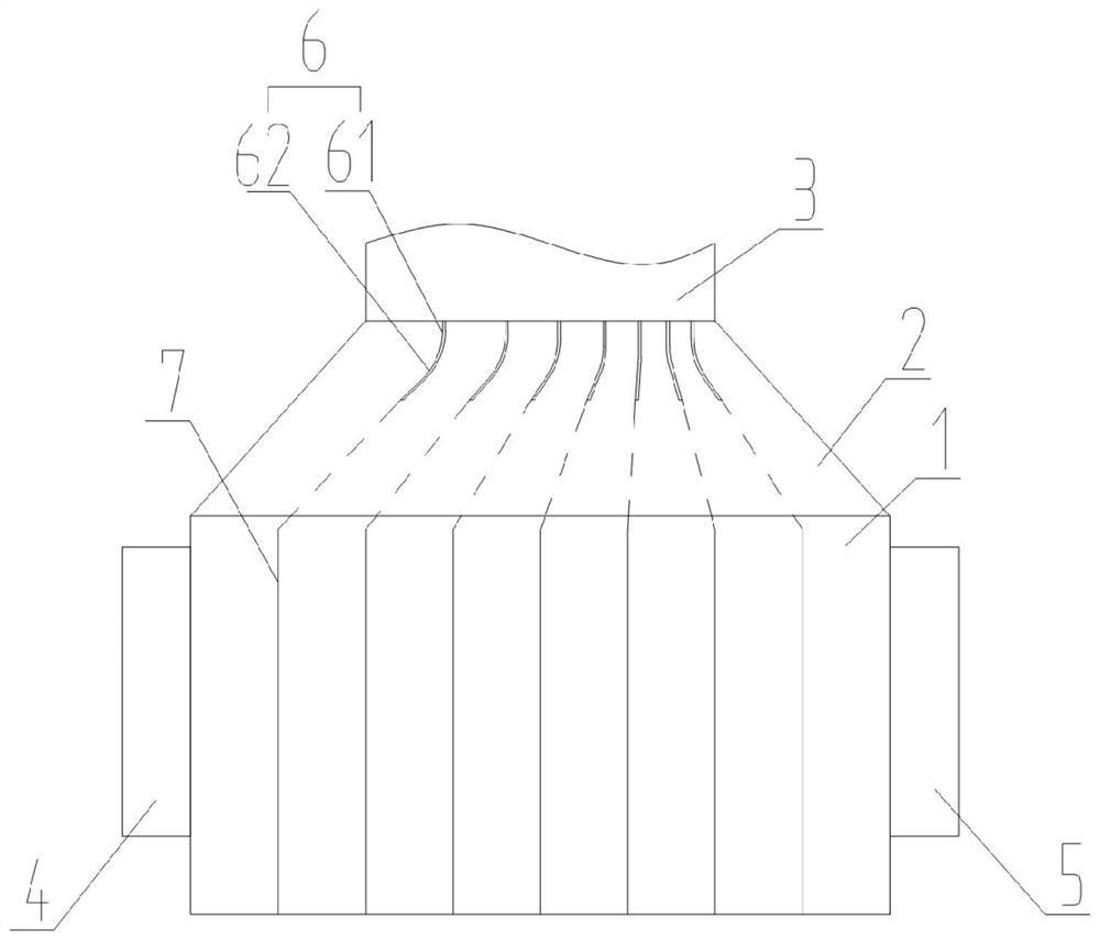
[0033] A diversion structure for condensers, such as figure 1 As shown, it includes a housing 1, and the upper part of the housing 1 is provided with a condenser throat 2, and the condenser throat 2 is connected to the exhaust port 3 of the low-pressure cylinder;

[0034] The housing 1 is provided with a cooling liquid inlet 4 and a cooling liquid outlet 5, and a heat exchange tube is arranged inside the housing 1, and the heat exchange tube communicates with the cooling liquid inlet 4 and the cooling liquid outlet 5 to form a cooling liquid circulation channel. fluid passage;

[0035] A number of deflectors 6 are arranged inside the condenser, and a number of baffles 7 are also arranged inside the shell 1. The steam enters the condenser throat 2 through the exhaust port 3 of the low-pressure cylinder, and passes through the deflector. The plate enters the space isolated by the partition to achieve heat exchange cooling.

[0036] In this embodiment, the condenser is a commo...

Embodiment 2

[0046] A kind of diversion method for condenser, adopts a kind of diversion structure for condenser of embodiment 1, comprises the following steps:

[0047] a. Use partitions to divide the inner cavity of the condenser shell into several equal cooling cavities. The cooling cavities are A1, A2, A3, A4...An in turn; inside the condenser along the cooling liquid inlet and The amount of steam condensed in each cooling cavity in the direction of the coolant outlet is Q1, Q2, Q3, Q4...Qn;

[0048] b. A number of deflectors are set inside the condenser, through which the interior of the condenser is divided into several guide channels along the direction of the coolant inlet and coolant outlet, and the guide channels are B1, B2, B3, B4... Bn;

[0049] c. The deflector is divided into a vertical part and an arc part, and the vertical part and the arc part are integrally formed. At the same time, the arc plate is arc-shaped along the vertical direction for diversion of steam.

[0050...


PUM


Abstract

The invention discloses a flow guide structure and a flow guide method for a condenser, and belongs to the technical field of steam turbine condenser devices for thermal power generation. The structure comprises a shell, a condenser throat part is arranged on the upper portion of the shell, and the condenser throat part is communicated with a low-pressure cylinder steam exhaust port. The shell is provided with a cooling liquid inlet and a cooling liquid outlet, a heat exchange pipe is arranged in the shell, and the heat exchange pipe is communicated with the cooling liquid inlet and the cooling liquid outlet to form a liquid passage for cooling liquid circulation; according to the flow guide structure for the condenser and the flow guide method, the problem that the traditional flow guide effect is poor is solved, especially the problem that a large amount of steam transversely flows in the shell in actual operation based on a traditional structure, and then larger steam resistance is caused is solved; and by means of the design of the flow guide plates and the partition plates, the cooling effect can be effectively better, the heat utilization efficiency is higher, and the efficient cooling effect is achieved.

Description

technical field [0001] The invention relates to a diversion structure and a diversion method for a condenser, belonging to the technical field of steam turbine condenser devices for thermal power generation. Background technique [0002] The condenser is the most important equipment in the cold end system of the steam turbine, and its performance directly affects the output of the unit and the energy consumption level of the unit. A condenser usually consists of a throat, and a shell below the throat. The exhaust steam of the steam turbine enters the shell through the expansion of the throat, and exchanges heat with the circulating water in the heat exchange tube to form a vacuum; therefore, the heat transfer coefficient of the condenser is improved, the performance of the condenser is improved, and the back pressure of the unit operation is reduced. Especially important in the design of the condenser. [0003] The vapor resistance on the shell side of the condenser is an ...

Claims


Application Information

Patent Timeline
Patent Type & Authority Applications(China)
IPC IPC(8): F28B9/02F28F9/22F28B1/02
CPCF28B9/02F28F9/22F28B1/02F28F2009/224
Inventor 阳欧颜强刘经武钟刚云文圆圆黄彪刘雄高晓亮姬艳云李开旺王忠房媛
Owner DONGFANG TURBINE CO LTD
Why Eureka
Try Eureka